
Figures & data
Figure 1. The schematic of the BTF system. (1) Air compressor, (2) gas valve, (3) buffer tank, (4) rotameter, (5) m-Dichlorobenzene gas generator, (6) mixed gas tank, (7) inlet gas sample port, (8) BTF column, (9) nutrient solution tank, (10) peristaltic pump, (11) packaging material, (12) outlet gas sample port
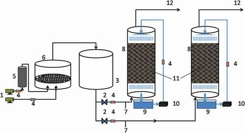
Figure 2. The effect of Zn(II) concentration on the growth of strains and the degradation of m-dichlorobenzene
Figure 3. The performance of the BTF
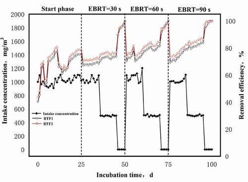
Figure 4. The content of polysaccharide (a) and protein (b) in EPS
Figure 5. C12O enzyme activity of the strain
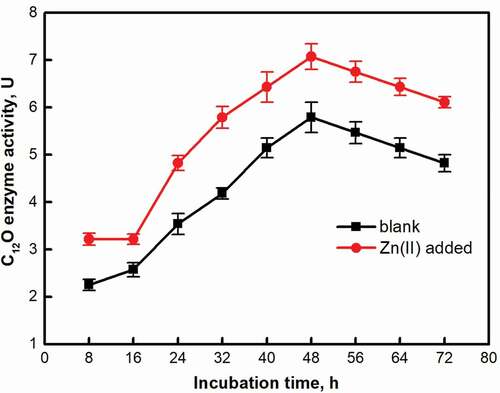
Figure 6. Zeta potential on the EPS surface
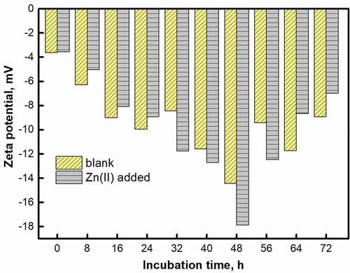
Figure 7. Fourier transform infrared spectrum of EPS
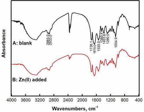
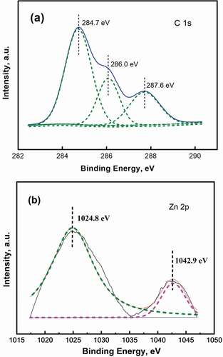
Figure 8. X-ray photoelectron spectrum of strain DH-1
Supplemental material