
Figures & data
Table 1. Summary of CAD/CAM materials used, their descriptions of class, manufacturers, and lot number.
Figure 1. (a) Scanned abutment, (b,c) designed sphero-cylindrical shape to be machined, (d) CAD/CAM materials investigated in this study before and after machining (inset shows the burs used in the two different machining protocols), (e) marginal strength test is performed with a laser extensometer, and (f) a view of a fractured specimen [Reprinted with permission from Elsevier].
![Figure 1. (a) Scanned abutment, (b,c) designed sphero-cylindrical shape to be machined, (d) CAD/CAM materials investigated in this study before and after machining (inset shows the burs used in the two different machining protocols), (e) marginal strength test is performed with a laser extensometer, and (f) a view of a fractured specimen [Reprinted with permission from Elsevier].](/cms/asset/cc46ed92-2f42-4f8b-88ca-6d44c4919749/iabo_a_1964969_f0001_c.jpg)
Figure 2. Scanning electron microscopy images of damaged surface on five different materials tested, in fine and rough protocol machining.
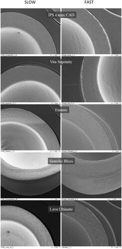
Figure 3. Light retardation illustrated using color scales from blue (0 nm, zero stress) to red (50 nm, high stress). The selected area for measurement is confined here to the region of the specimen in which there is light transmission (the upper region is excluded due to the opacity of the piston as it is inserted into the specimen lumen).
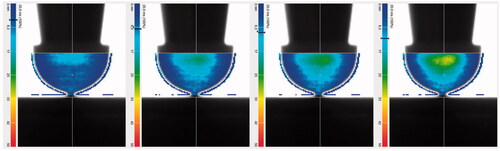
Figure 4. (a) FE Analysis of the maximum principal stress distribution in the sphero-cylindrical model crown for the material IPS e.max® CAD; (b) principal stress trajectory plots presenting the circumferential stress directions; and (c) cross-section showing the maximum principal stress distribution through the thickness.
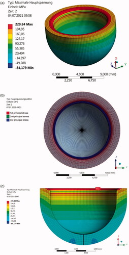
Table 2. Weibull parameters were calculated for the inner marginal strength obtained from FE simulation of the obtained fracture forces in the in-vitro test.