
Figures & data
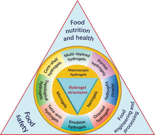
Table 1. Classification of hydrogels
Figure 1. ‘Egg-box’ structure of hydrogel formed between G residues of alginate and CaCitation2+. Dimensions are not drawn to scale
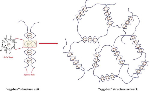
Figure 2. Schematic of the micellar copolymerization of HA-gels. Dimensions are not drawn to scale
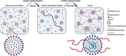
Figure 3. Schematic diagram of κ-carrageenan hydrogel formation via aggregation of helices. Dimensions are not drawn to scale
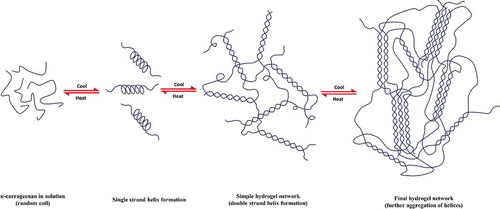
Figure 4. Structures of polyrotaxane and pseudo-polyrotaxane formed via CD-based host-guest interactions
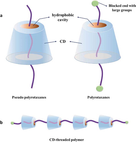
Figure 5. Formation of polyrotaxane hydrogels from α-CD and high molecular weight PEG
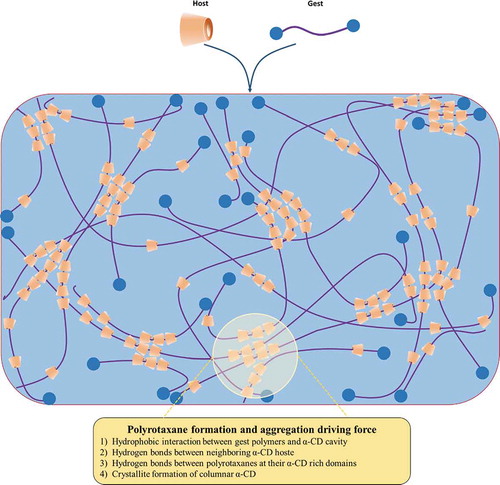
Figure 6. Schematic diagram of the four common free-radical polymerization methods. Dimensions are not drawn to scale
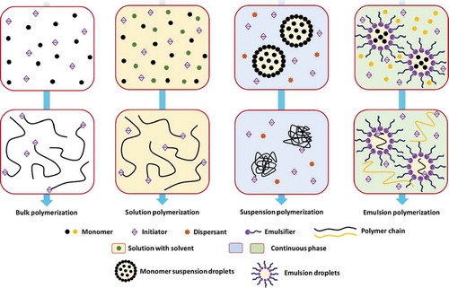
Figure 7. Schematic diagram of the hydrogels prepared via UV-induced free-radical polymerization. (a) Solution polymerization pathway, and (b) emulsion/micellar polymerization pathway. Dimensions are not drawn to scale
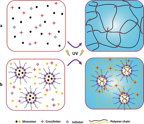
Figure 8. Illustrations of core-shell-structured hydrogels
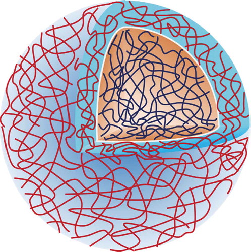
Figure 9. Different types of multi-layered hydrogels
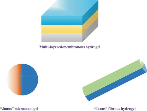
Figure 10. Three different hydrogel-nanoparticle structural designs exist: a) micro- or nano-sized hydrogel particles stabilizing inorganic or polymer nanoparticles, b) nanoparticles non-covalently immobilized in a hydrogel matrix, and c) nanoparticles covalently immobilized in a hydrogel matrix. Reproduced from ref. [Citation430] with permission. Copyright 2015 WILEY-VCH Verlag GmbH & Co. KGaA, Weinheim
![Figure 10. Three different hydrogel-nanoparticle structural designs exist: a) micro- or nano-sized hydrogel particles stabilizing inorganic or polymer nanoparticles, b) nanoparticles non-covalently immobilized in a hydrogel matrix, and c) nanoparticles covalently immobilized in a hydrogel matrix. Reproduced from ref. [Citation430] with permission. Copyright 2015 WILEY-VCH Verlag GmbH & Co. KGaA, Weinheim](/cms/asset/a9e29764-a796-468e-ac29-2d01769f9618/lfri_a_1858313_f0010_oc.jpg)
Figure 11. Five main approaches used to obtain hydrogel-nanoparticle conjugates with uniform distributions: 1) hydrogel formation in a nanoparticle suspension, 2) physically embedding the nanoparticles into a hydrogel matrix after gelation, 3) reactive nanoparticle formation within a preformed gel, 4) crosslinking using nanoparticles to form hydrogels, 5) gel formation using nanoparticles, polymers, and distinct gelator molecules. Reproduced from ref. [Citation430] with permission. Copyright 2015 WILEY-VCH Verlag GmbH & Co. KGaA, Weinheim
![Figure 11. Five main approaches used to obtain hydrogel-nanoparticle conjugates with uniform distributions: 1) hydrogel formation in a nanoparticle suspension, 2) physically embedding the nanoparticles into a hydrogel matrix after gelation, 3) reactive nanoparticle formation within a preformed gel, 4) crosslinking using nanoparticles to form hydrogels, 5) gel formation using nanoparticles, polymers, and distinct gelator molecules. Reproduced from ref. [Citation430] with permission. Copyright 2015 WILEY-VCH Verlag GmbH & Co. KGaA, Weinheim](/cms/asset/e0464394-feab-4f89-868e-df45fc6653d5/lfri_a_1858313_f0011_oc.jpg)
Figure 12. Schematic illustrations of an MMC hydrogel structure. The MC hydrogel structure is similar to that of the MMC hydrogel structure as long as the macromolecular microsphere is replaced by a microgel
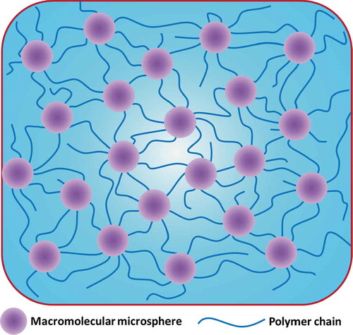
Figure 13. Main possible interactions contributing to the formation and toughening of MMC hydrogels. Reproduced from ref. [Citation452] with permission. Copyright 2013 American Chemical Society
![Figure 13. Main possible interactions contributing to the formation and toughening of MMC hydrogels. Reproduced from ref. [Citation452] with permission. Copyright 2013 American Chemical Society](/cms/asset/5de7dff1-e8f4-494e-b34b-1ed63b007320/lfri_a_1858313_f0013_oc.jpg)
Figure 14. Schematic illustrations of an SIPN (A) and a FIPN (B)
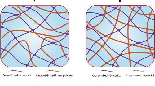
Figure 15. Schematic illustrations of an AB-type-crosslinked polymer
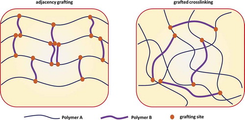
Figure 16. Schematic of the in situ and sequential pathways used to prepare IPNs and semi-IPNs. Reproduced from ref. [Citation464] with permission. Copyright 2011 Elsevier
![Figure 16. Schematic of the in situ and sequential pathways used to prepare IPNs and semi-IPNs. Reproduced from ref. [Citation464] with permission. Copyright 2011 Elsevier](/cms/asset/2c78e793-8773-46ee-9405-f2872c94cf54/lfri_a_1858313_f0016_oc.jpg)
Figure 17. Topological hydrogel structure of typical figure-eight crosslinked networks
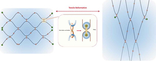
Figure 18. Schematic illustration of tetra-PEG hydrogels
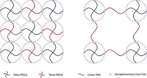
Figure 19. Schematic representation of emulsion-filled gels and emulsion particulate gels. Reproduced from ref. [Citation508] with permission. Copyright 2019 Elsevier
![Figure 19. Schematic representation of emulsion-filled gels and emulsion particulate gels. Reproduced from ref. [Citation508] with permission. Copyright 2019 Elsevier](/cms/asset/09af048c-bce6-4d70-b6f5-1f98c3cebb85/lfri_a_1858313_f0019_oc.jpg)