277
Views
0
CrossRef citations to date
0
Altmetric
Original

BIOPHYSICAL PROPERTIES*

, B.Sc., M.D., C.M., Ph.D., F.R.C.P.(C).
Pages 375-396 | Published online: 11 Jul 2009

Figures & data

Figure 15. Nylon membrane artificial cells shortly after being placed in hypertonic solution. (From Chang, 1964. Copyright 1964 by the American Association for the Advancement of Science.)
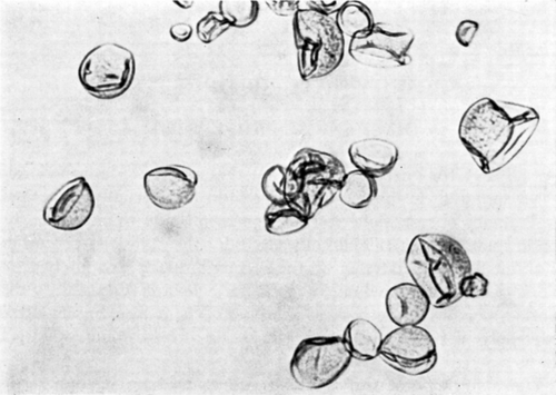
Figure 15. Nylon membrane artificial cells shortly after being placed in hypertonic solution. (From Chang, 1964. Copyright 1964 by the American Association for the Advancement of Science.)

Figure 16. Deformability of a nylon membrane artificial cell. The artificial cell, about 100μ in diameter and suspended in saline, is moving from left to right along a tapering glass capillary and is subjected to a hydrostatic pressure gradient from left to right. Note flattening of upstream surface, bulging of downstream surface, longitudinal folding of membrane, and smaller volume of artificial cell as a result of filtration of fluid through downstream surface into capillary. (From Chang, 1965; Chang et al., 1966. Courtesy of the National Research Council of Canada.)
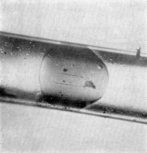
Figure 16. Deformability of a nylon membrane artificial cell. The artificial cell, about 100μ in diameter and suspended in saline, is moving from left to right along a tapering glass capillary and is subjected to a hydrostatic pressure gradient from left to right. Note flattening of upstream surface, bulging of downstream surface, longitudinal folding of membrane, and smaller volume of artificial cell as a result of filtration of fluid through downstream surface into capillary. (From Chang, 1965; Chang et al., 1966. Courtesy of the National Research Council of Canada.)

Figure 17. Deformability of nylon membrane artificial cells. Two artificial cells about 1 mm in diameter, suspended in silicone oil and placed in Couette flow apparatus. Left to right, zero flow; onset of Couette flow; collision; separation after collision; cessation of flow. (From Chang, 1965.)

Figure 17. Deformability of nylon membrane artificial cells. Two artificial cells about 1 mm in diameter, suspended in silicone oil and placed in Couette flow apparatus. Left to right, zero flow; onset of Couette flow; collision; separation after collision; cessation of flow. (From Chang, 1965.)

Figure 18. Schematic representation of cell elastometer. (From Jay and Edwards, 1968. Courtesy of the National Research Council of Canada.)
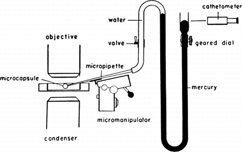
Figure 18. Schematic representation of cell elastometer. (From Jay and Edwards, 1968. Courtesy of the National Research Council of Canada.)

Figure 19. Schematic representation of artificial cell with a portion of the membrane drawn into the elastometer micropipette. Parameters involved are described in detail in text. (From Jay and Edwards, 1968. Courtesy of the National Research Council of Canada.)
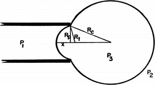
Figure 19. Schematic representation of artificial cell with a portion of the membrane drawn into the elastometer micropipette. Parameters involved are described in detail in text. (From Jay and Edwards, 1968. Courtesy of the National Research Council of Canada.)

Figure 20. Upper, microphotograph of artificial cell with a portion of the membrane drawn into the elastometer micropipette (a much higher magnification was used in the experiments). Lower, a ruptured artificial cell showing the absence of any rigidity in the membrane. Spherical shape is maintained by the colloid osmotic pressure. (From Jay and Edwards, 1968. Courtesy of the National Research Council of Canada.)
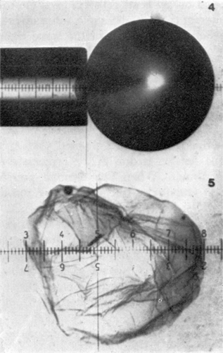
Figure 20. Upper, microphotograph of artificial cell with a portion of the membrane drawn into the elastometer micropipette (a much higher magnification was used in the experiments). Lower, a ruptured artificial cell showing the absence of any rigidity in the membrane. Spherical shape is maintained by the colloid osmotic pressure. (From Jay and Edwards, 1968. Courtesy of the National Research Council of Canada.)

Figure 21. Pressure-deformation curves for various sizes of artificial cells. Rp=105μ. Note the abrupt change in slope at high pressures. (From Jay and Edwards, 1968. Courtesy of the National Research Council of Canada.)
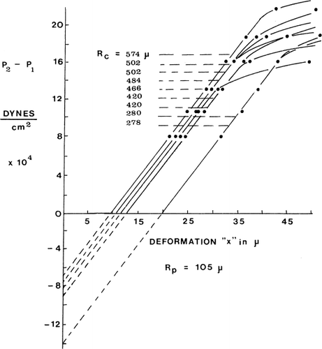
Figure 21. Pressure-deformation curves for various sizes of artificial cells. Rp=105μ. Note the abrupt change in slope at high pressures. (From Jay and Edwards, 1968. Courtesy of the National Research Council of Canada.)

Figure 22. Left, permeability of nylon membrane artificial cells to nonelectrolytes. Right, permeability of nylon membrane artificial cells to electrolyes: KCl, NaCl, and LiCl. (From Chang, 1965.)
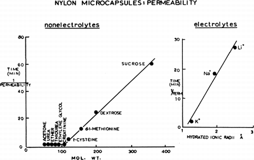
Figure 22. Left, permeability of nylon membrane artificial cells to nonelectrolytes. Right, permeability of nylon membrane artificial cells to electrolyes: KCl, NaCl, and LiCl. (From Chang, 1965.)

Figure 23. Upper, percentage of collapsed nylon membrane artificial cells as a function of glucose concentration in the medium. Abscissae: concentration of glucose in suspending medium. Ordinates (plotted on probit scale): percentage of artificial cells found to be collapsed in the glucose medium. Lower, percentage of collapsed artificial cells in nonelectrolyte solutions plotted on probit scale. •=sucrose; ▴=glucose; ○=propylene glycol; ▾=ethylene glycol. (From Chang, 1965; Chang and Poznansky, 1968. Courtesy of Interscience Publishers, New York.)
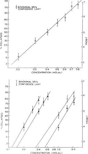
Figure 23. Upper, percentage of collapsed nylon membrane artificial cells as a function of glucose concentration in the medium. Abscissae: concentration of glucose in suspending medium. Ordinates (plotted on probit scale): percentage of artificial cells found to be collapsed in the glucose medium. Lower, percentage of collapsed artificial cells in nonelectrolyte solutions plotted on probit scale. •=sucrose; ▴=glucose; ○=propylene glycol; ▾=ethylene glycol. (From Chang, 1965; Chang and Poznansky, 1968. Courtesy of Interscience Publishers, New York.)

Figure 24. Analysis of equivalent pore radius for nylon membrane artificial cells prepared by the standard procedure. (For explanation see text.) Each of the 4 theoretical curves relates the ratio of reflection coefficients for a given pair of solutes to equivalent pore radii from 0 to 30 Å. The plotted points (mean±standard deviation) are experimentally determined values for 4 solute pairs. (From Chang and Poznansky, 1968. Courtesy of Interscience Publishers, New York.)
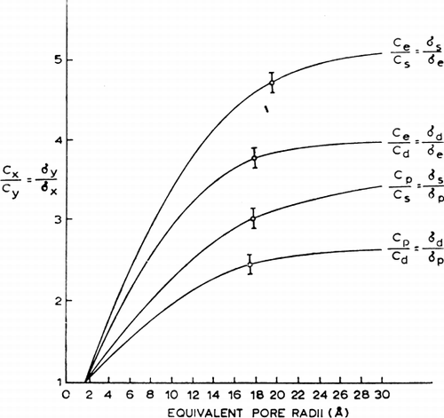
Figure 24. Analysis of equivalent pore radius for nylon membrane artificial cells prepared by the standard procedure. (For explanation see text.) Each of the 4 theoretical curves relates the ratio of reflection coefficients for a given pair of solutes to equivalent pore radii from 0 to 30 Å. The plotted points (mean±standard deviation) are experimentally determined values for 4 solute pairs. (From Chang and Poznansky, 1968. Courtesy of Interscience Publishers, New York.)

Figure 25. Upper, rapid mixing and sampling apparatus used in the determination of permeability constants. Rotating arm (1) opens valve (1) to air pressure and triggers the rapid injection of artificial cell suspension and test solution through the mixing chamber into a collecting beaker. After a predetermined interval, rotaring arm (2) of kymograph triggers the sampling syringe to aspirate an aliquot of artificial cell free supernatant through the filter. Lower, permeability constants, example of results obtained. Rate of entry of solute measured as the rate of decrease of radioactivity in the suspending medium. Concentration of artificial cells (diameter 210.9μ±75.0μ) in the suspension after the addition of an equal volume of the test solution is 55,000/ml. (From Chang and Poznansky, 1968. Courtesy of Interscience Publishers, New York.)
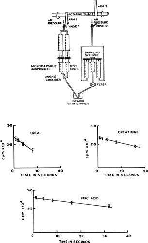
Figure 25. Upper, rapid mixing and sampling apparatus used in the determination of permeability constants. Rotating arm (1) opens valve (1) to air pressure and triggers the rapid injection of artificial cell suspension and test solution through the mixing chamber into a collecting beaker. After a predetermined interval, rotaring arm (2) of kymograph triggers the sampling syringe to aspirate an aliquot of artificial cell free supernatant through the filter. Lower, permeability constants, example of results obtained. Rate of entry of solute measured as the rate of decrease of radioactivity in the suspending medium. Concentration of artificial cells (diameter 210.9μ±75.0μ) in the suspension after the addition of an equal volume of the test solution is 55,000/ml. (From Chang and Poznansky, 1968. Courtesy of Interscience Publishers, New York.)

Table 1. Nylon Membrane Artificial Cells: Permeability Data

Figure 26. Rate of equilibration of 22Na across artificial cells. Control nylon membrane artificial cells (•) compared to lipid-coated nylon membrane artificial cells (▴). (From Chang, 1969b.)
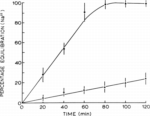
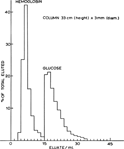
Figure 26. Rate of equilibration of 22Na across artificial cells. Control nylon membrane artificial cells (•) compared to lipid-coated nylon membrane artificial cells (▴). (From Chang, 1969b.)
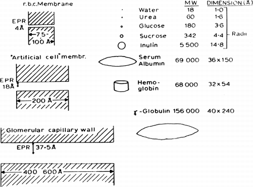
Figure 27. Column with dimensions as shown, packed with nylon membrane cells of mean diameter about 90μ, prepared by the standard method using 1% (v/v) Span 85 and jumbo magnetic stirrer speed setting of 1. Flow rate 0.09 ml/min; eluate collected in 0.2 ml fractions. (From Chang, 1965.)

Figure 27. Column with dimensions as shown, packed with nylon membrane cells of mean diameter about 90μ, prepared by the standard method using 1% (v/v) Span 85 and jumbo magnetic stirrer speed setting of 1. Flow rate 0.09 ml/min; eluate collected in 0.2 ml fractions. (From Chang, 1965.)

Figure 28. Schematic representation comparing equivalent pore radius (EPR) to solute molecules.

Figure 28. Schematic representation comparing equivalent pore radius (EPR) to solute molecules.

Reprints and Corporate Permissions

Please note: Selecting permissions does not provide access to the full text of the article, please see our help page How do I view content?

To request a reprint or corporate permissions for this article, please click on the relevant link below:

Academic Permissions

Please note: Selecting permissions does not provide access to the full text of the article, please see our help page How do I view content?

Obtain permissions instantly via Rightslink by clicking on the button below:

If you are unable to obtain permissions via Rightslink, please complete and submit this Permissions form. For more information, please visit our Permissions help page.