Figures & data
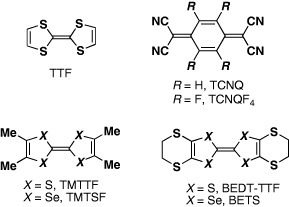
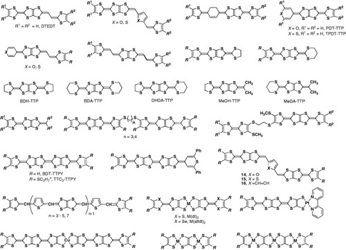
Scheme 1 Molecular structures of TTF and TCNQ derivatives in this paper.
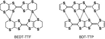
Scheme 2 Lateral interactions in BEDT-TTF and BDT-TTP conductors.
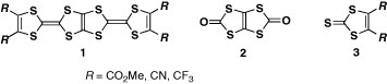
Scheme 3 Molecular structures of 1–3.
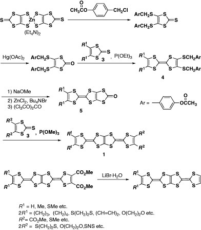
Scheme 4 Synthesis of BDT-TTP derivatives.
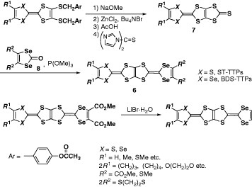
Scheme 5 Synthesis of selenium analogs of BDT-TTP.
Scheme 6 Synthesis of 5 and11 via Me3 Al-promoted reaction.
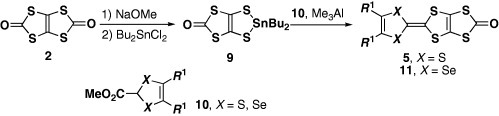
Figure 1 Top (a) and side (b) views of the molecular structure of BDT-TTP. (Reprinted with permission from [Citation10].)
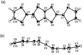
Table 1 Redox potentialsa of BDT-TTP derivatives and the related compounds (scheme ).
Scheme 7 Molecular structures of the donors listed in table 1.
Scheme 8 Molecular structures of BDT-TTP derivatives listed in table 2.
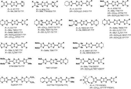
Table 2 Molecular packing patterns and electrical properties of conducting salts based on BDT-TTP derivatives (scheme ); σrt refers to room-temperature conductivity.
Figure 2 Crystal structure of (BDT-TTP)2SbF6 where dotted lines represent intermolecular S···S contacts. (Reprinted with permission from [Citation45].)
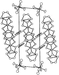
Figure 3 Donor sheet structure of (BDT-TTP)2SbF6. The intermolecular overlap integrals are a1=25.1, a2=25.3, c=0.8, p1=7.9 and p2=8.6× 10⁻³. (Reprinted with permission from [Citation45].)
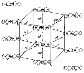
Figure 4 Fermi surface of (BDT-TTP)2SbF6 calculated from the transfer integrals obtained (a) theoretically and (b) from optical experiments.
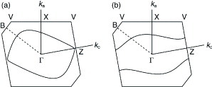
Figure 5 Crystal structure of (BDT-TTP)3I. (Reprinted with permission from [Citation50].)
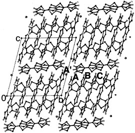
Figure 6 Donor-sheet structure of (BDT-TTP)3[MIICl4](EtOH)x (M=Co, Mn, Zn, x≈1.0). (Reprinted with permission from [Citation51].)
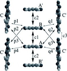
Figure 7 Donor-sheet structure of (CH-TTP)(I3)0.31. The intermolecular overlap integrals are c=−4.32, p=22.2, r=7.61 and b=12.0× 10⁻³. (Reprinted with permission from [Citation52].)
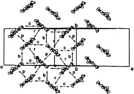
Figure 8 (a) Conducting sheet structure of θ-(BTM-TTP)2SbF6 viewed along the donor long axis. The intermolecular overlaps between HOMOs are a=7.7, p=6.5 and q=3.6× 10⁻³. (b) The overlap mode of the donors in the stack. (Reprinted with permission from [Citation54].)
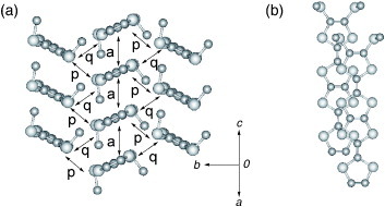
Figure 9 Donor-sheet structure of (TMEO-TTP)2Au(CN)2. The intermolecular overlap integrals are c=4.2, a1=18.3, a2=7.3, p1=−11.5 and p2=−9.7× 10⁻³. (Reprinted with permission from [Citation56].)
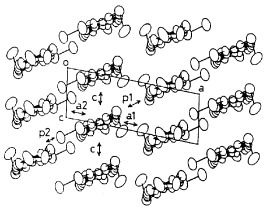
Figure 10 Electrical properties of (TMEO-TTP)2Au(CN)2. (Reprinted with permission from [Citation56].)
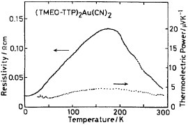
Figure 11 Crystal structure of (TMEO-ST-TTP)Au(CN)2. (Reprinted with permission from [Citation59].)
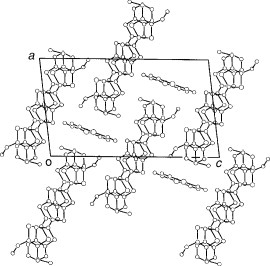
Figure 12 Overlap modes of donor molecules in (TMEO-ST-TTP)Au(CN)2. (Reprinted with permission from [Citation59].)
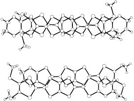
Figure 13 Overlap modes of donor molecules in (TMEO-ST-TTP)2AsF6. (Reprinted with permission from [Citation60].)
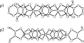
Figure 14 The Fermi surface of (BEDT-TTP)2I3.
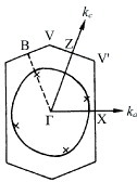
Figure 15 Donor sheet structure of (C2TET-TTP)2ClO4. The intermolecular overlap integrals are b=−20.2, p1=7.0, p2=2.1, p3=−0.9 and p4=9.6× 10⁻³. (Reprinted with permission from [Citation28].)
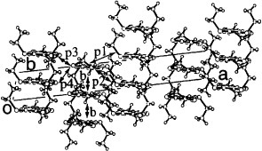
Figure 16 Donor sheet structure of (C4TET-TTP)I3. The intermolecular overlap integrals are c=−16.6, p1=−0.6 and p2=0.03× 10⁻³. (Reprinted with permission from [Citation28].)
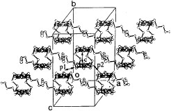
Figure 17 Temperature dependence of resistivity of (TTM-TTP)I3 and (TTM-TTP)(I3)5/3.
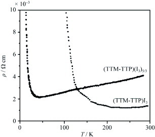
Figure 18 Stacking structure of (TTM-TTP)I3. (Reprinted with permission from [Citation64].)
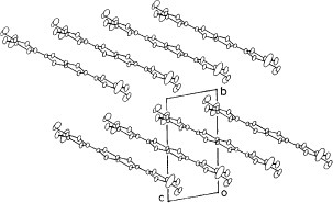
Figure 19 Overlap modes of donor molecules in (CPTM-TTP)4AsF6.
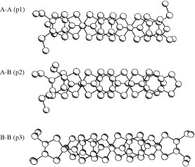
Table 3 Molecular packing patterns and electrical properties of conducting salts based on TTP donors containing non-TTF moieties (scheme ).
Scheme 9 Molecular structures of analogous TTP derivatives.
Scheme 10 Molecular structures of analogous TTP derivatives listed in table 3.
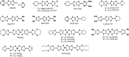
Figure 20 HOMO of DTEDT (left) and BDT-TTP (right).
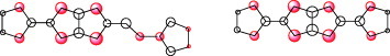
Figure 21 Temperature dependence of resistivity of (DTEDT)3Au(CN)2. (Reprinted with permission from [Citation83].)
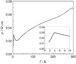
Figure 22 Crystal structure of (DTEDT)3Au(CN)2. (Reprinted with permission from [Citation83].)
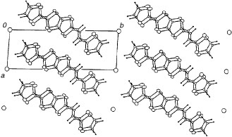
Figure 23 Donor-sheet structure of (DTEDT)3Au(CN)2. The intermolecular overlap integrals are c1=−19.2, c2=−19.9, c3=−10.8, a1=−1.5, a2=−1.3, a3=−0.7, p1=−3.8, p2=−3.4 and p3=−6.9× 10⁻³.
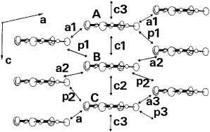
Figure 24 Donor-sheet structure of (ET-PDT)4PF6 (cn) (Reprinted with permission from [Citation89].)
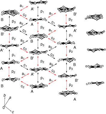
Figure 25 Overlap modes of the donor molecules in (ET-PDT)4PF6(cn). (Reprinted with permission from [Citation89].)
Figure 26 A schematic drawing of overlaps between the donor molecules in (ET-PDT)4PF6(cn); bars and broken lines denote the donor molecules projected along the long molecular axis and relatively large intra- and interstack interactions, respectively.
Figure 27 Crystal structure of (TM-TPDS)2AsF6 projected onto the bc-plane. Dotted lines show the intermolecular S···S contacts.
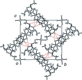
Figure 28 Crystal structure of (SM-PDT)PF6(PhCl)x viewed along the c-axis. Disordered solvent molecules are located in the cavity.
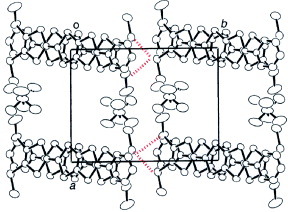
Figure 29 Donor column structure viewed along the a-axis and definition of the overlap integrals of (SM-PDT)PF6(PhCl)x. The intermolecular overlap integrals are c1=6.3, c2=8.1, p1=−2.3, p2=0.00 and b=−0.8× 10⁻³. (Reprinted with permission from [Citation93].)
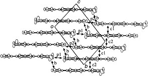
Figure 30 Molecular structure of BDA-TTP in (BDA-TTP)2SbF6; the dihedral angles φ1 and φ2 are 47.9 and 33.2°, respectively. (Reprinted with permission from [Citation98].)
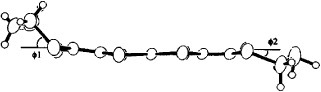
Figure 31 Temperature dependence of normalized resistivity in BDA-TTP superconductors. (Reprinted with permission from [Citation98].)
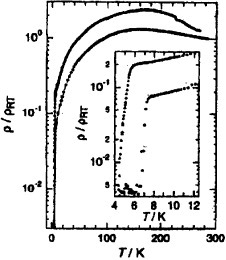
Figure 32 Overlap mode in a dimer of (CPDT-TTF)2(AsF6)0.72.
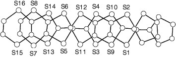
Figure 33 Band structure and Fermi surface of (MeDH-TTP)2AsF6. (Reprinted with permission from [Citation149].)
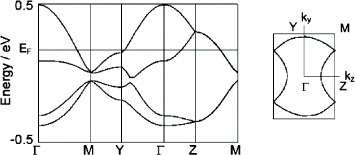
Figure 34 Temperature dependence of resistivity of TTC3-TTPY after 7 min iodine doping followed by annealing at 75 °C. (Reprinted with permission from [Citation110].)
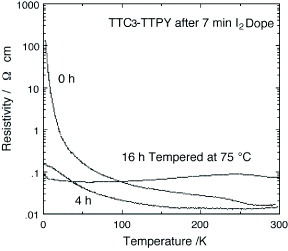
Figure 35 Crystal structure of Ni(tmdt)2 viewed along the molecular (a) short and (b) long axis. (Reprinted with permission from ref. [Citation137].)
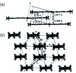
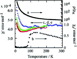
Figure 36 Resistivities and susceptibilities of Au(tmdt)2: (a), resistivity of compacted pellet (ρrt=0.067Ω cm); (b), spin susceptibility χs by ESR; (c)–(e), magnetic susceptibilities by SQUID at 30 kOe (blue, <300 K), 10 kOe (red, <200 K) and 3 kOe (green, <200 K). (Reprinted with permission from [Citation13Citation9].)