Figures & data
Table 1. Parameters used for fabricating chitosan, PLGA, gelatin and PCL fibrous scaffolds.
Figure 1. Schematics of double-ejection electrospinning (A), triple-layer artificial blood vessel scaffold (B) and cross-linking process (C).
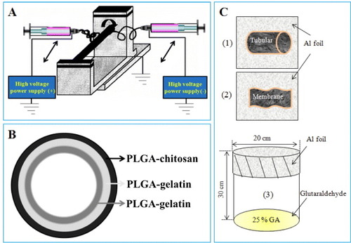
Figure 2. SEM morphology of the outer layer of the artificial blood vessel: chitosan (a), PLGA (b), PLGA–chitosan (c) and cro-PLGA–chitosan scaffolds (d).
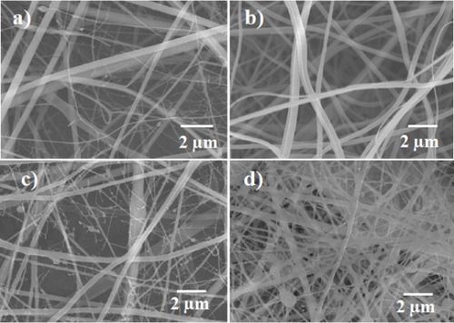
Figure 3. SEM morphology of the intermediate layer of the artificial blood vessel: gelatin (a), PLGA (b), PLGA–gelatin (c) and cro-PLGA–gelatin scaffolds (d).
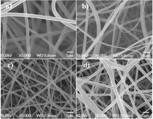
Figure 4. SEM morphology of the inner layer of the artificial blood vessel: gelatin (a), PCL (b), PCL–gelatin (c) and cro-PCL–gelatin scaffolds (d).
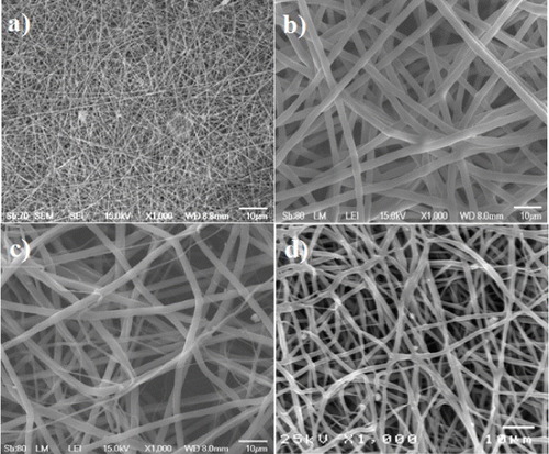
Figure 5. Artificial blood vessels with different inner diameters (a), cross-section (b), the three layers of the PCL–gelatin/PLGA–gelatin/PLGA–chitosan fibrous tube stained in different colors (c), (d) and the bilayers of the PCL–gelatin/PLGA–chitosan fibrous tube (e).
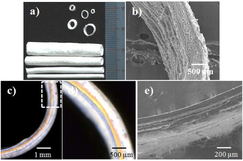
Figure 6. Stress–strain curves and corresponding SEM morphology of PCL–gelatin/PLGA–gelatin/PLGA–chitosan ABV scaffold: non-cross-linked (a1-2) and cross-linked (b1-2).
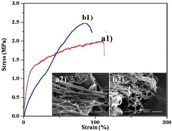
Figure 7. Burst strength of non-cross-linked and cross-linked PCL–gelatin/PLGA–gelatin/PLGA–chitosan scaffolds.
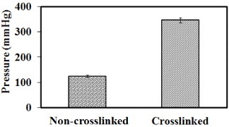
Figure 8. Cytotoxicity of electrospun PCL–gelatin, cro-PCL–gelatin, gelatin–PLGA , cro-gelatin–PLGA, PLGA–chitosan and cro-PLGA–chitosan scaffolds.
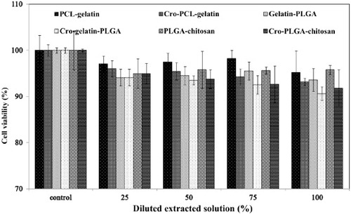
Figure 9. Optical absorbance of fibroblast cells seeded on PLGA–chitosan, cro-PLGA–chitosan and TCPS or endothelial cells seeded on PCL–gelatin, cro-PCL–gelatin and TCPS after 1, 3 and 5 days of incubation.
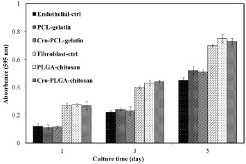
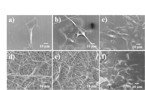
Figure 10. SEM morphology of fibroblast cells seeded on TCPS ((a), (b and (c)) and on cross-linked electrospun PLGA–chitosan scaffolds ((d), (e) and (f)) after 1, 3 and 5 days of incubation.
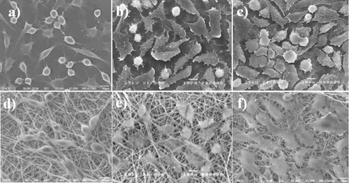
Figure 11. SEM morphology of endothelial cells seeded on TCPS ((a), (b) and (c)) and on cross-linked PCL–gelatin scaffolds ((d), (e) and (f)) after 1, 3 and 5 days of incubation.