Figures & data
Table 1. Requirements of metals for medical devices.
Table 2. Specified titanium alloys.
Figure 1 Causes of fracture of metals in medicine: (i) larger plastic deformation than the elongation to fracture is applied by medical doctor at the operation site; (ii) multiple plastic deformation is applied if the first bending by the medical doctor at the operation site is unsuccessful; (iii) alloy fatigue; (iv) large crevices as a result of corrosion work initiate fracture.
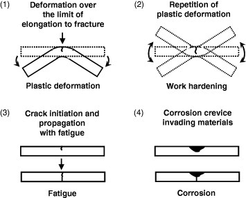
Figure 2 When fractured bone is fixed with a metallic bone fixator, such as a bone plate and screws and bone nail, the load to the fixation part during healing is mainly received by the metallic fixators because of the difference in the Young's moduli.
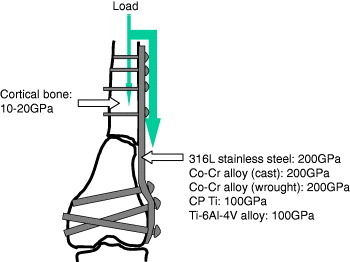
Figure 3 Elastic moduli of β-type alloys [Citation4].
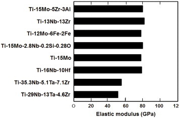
Figure 4 Dependence of Young's modulus of Ti porous body on porosity (left) and scanning electron photographs of porous Ti (right).
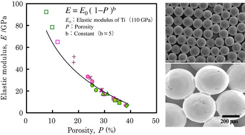
Figure 5 Porous Ti body in which the pores are filled with ultrahigh-molecular-weight polyethylene.
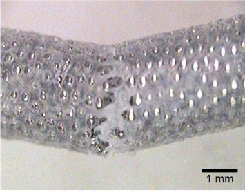
Figure 6 Early-stage fractures of self-expanding Ti–Ni femoral stents in service observed by x-ray examination [Citation10].
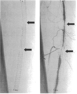
Figure 7 Severe pitting and crevice corrosion observed in Ti–Ni alloys in stent grafts [Citation18].
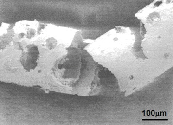
Figure 8 Concept of the development of alloys with low magnetic susceptibility. Alloying paramagnetic metal with diamagnetic metal (a), precipitation of a diamagnetic or low magnetic susceptibility phase in a paramagnetic matrix phase (b), and formation of composite of paramagnetic metal and diamagnetic material (c).
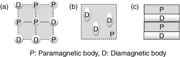
Figure 9 Effects of Nb content and constituent phases on the magnetic susceptibility of Zr–Nb alloy.
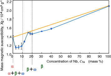
Figure 10 Magnetic susceptibilities of metals used for medical devices and Zr–Nb and Zr–Mo alloys.
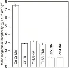
Figure 11 Mechanical properties of Zr–Nb alloys versus Nb content.
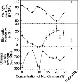
Figure 12 Surface modification techniques by both dry and wet processes used in research and industry.
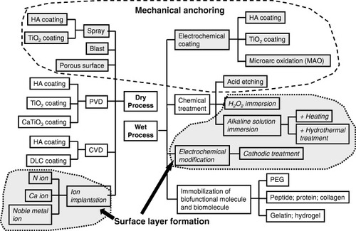
Figure 13 Research to improve hard-tissue compatibility involves two approaches based on the resultant surface layer: a calcium phosphate layer with the thickness in the micrometer scale and a surface-modified layer with the thickness in the nanometer scale.
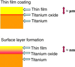
Figure 14 Schematics of chemical bonding and mechanical anchoring connection between bone and implanted material.
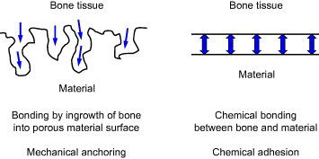
Figure 15 History of surface modification techniques to improve hard-tissue compatibility at the research level and estrangement in surface modification techniques between research and commercialization.
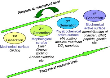
Figure 16 Relative concentration of elements in Zr-coated Ti, Zr and Ti determined by x-ray photoelectron spectroscopy [Citation62].
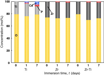
Figure 17 Chemical structure of poly(ethylene glycol).
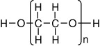
Figure 18 The cathodic potential was applied to Ti; during charging, the terminated PEGs electrically migrate to and are deposited on the Ti cathode.
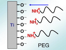
Figure 19 PEG immobilization by electrodeposition on the Ti surface and inhibition of platelet adhesion by immobilization [Citation100].
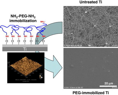
Figure 20 Schematic of the immobilization of RGD on PEG electrodeposited on Ti surface. To immobilize RGD, PEG with an –NH2 group and a –COOH group (NH2–PEG–COOH) must be employed. The –NH2 group is required to bind with the metal oxide on the metal surface, whereas the –COOH group binds RGD.
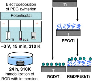
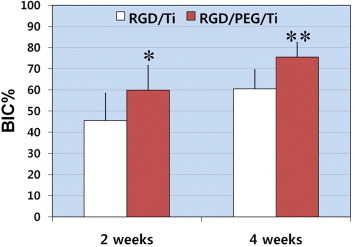
Figure 21 Mean percentage of the bone-to-implant contact (BIC%) over all threads of implants 2 and 4 weeks after implantation (∗p < 0.05, ∗∗p < 0.01) [Citation102]. RGD/PEG/Ti implants displayed significantly higher BIC% values in all threads and in the total lateral length compared with RGD/Ti implants at 2 and 4 weeks of healing.