Figures & data
Figure 1 Structures of DSA host and stylylamine dopant (Ar and R denote an arylene group and a substituent, respectively).
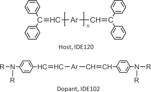
Figure 2 Structures of arylamine dopants (Ar and R denote an arylene group and a substituent, respectively).
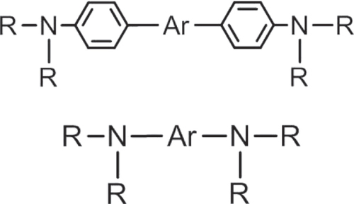
Figure 3 Energy diagram and excited level of each layer in an OLED with an EEL.
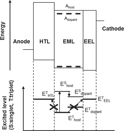
Table 1 Performance of BD-6 and BD-7 devices with or without an EEL (J = 10 mA cm−2).
Figure 4 Transient EL curves of devices 1 and 3: (a) transient EL curves as a function of log-scaled time; (b) inverse square root of transient EL intensity as a function of linear-scaled time.
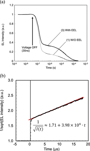
Figure 5 S′ of BD-C doped host film with a thickness of 100 nm.
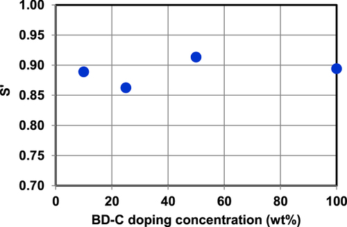
Table 2 Material properties of the four BDs.
Table 3 Device performance at a current density of 10 mA cm−2.
Figure 6 (a) V-J curves and (b) J-L/J curves.
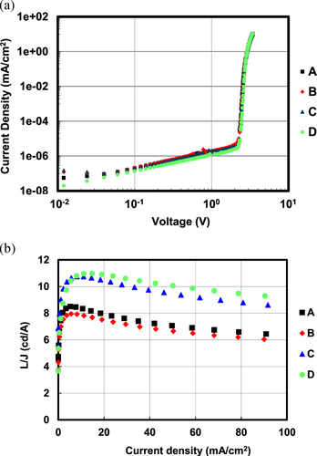
Figure 7 (a) Impedance spectroscopy results and (b) transient EL decay curves.
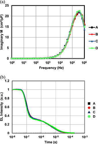
Figure 8 Calculated photonic mode density of a fluorescent blue device.
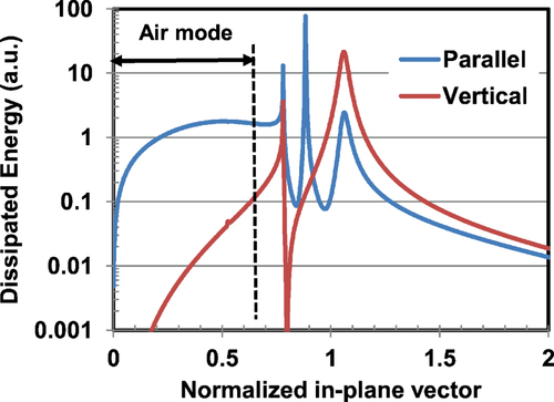
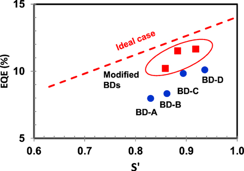
Figure 9 Relationship between orientation factor S′ and external quantum efficiency of an OLED (blue circle: results of BD-A–D; red square: modified BDs; red dotted line: ideal case with 100% of PLQY, 40% of singlet exciton formation ratio).