Figures & data
Figure 1. (a) An icosahedral phase particle oriented along a zone axis containing a fivefold and a twofold reciprocal vector perpendicular to each other, in a Mg-6Zn-1Ho (at%) alloy extruded at 230 °C. The inset shows the corresponding diffraction pattern. (b) Two icosahedral phase particles in a Mg-2.5Zn-0.5Y (at%) alloy solutionized at 460 °C for 15 h followed by annealing first at 250 °C and then at 400 °C. The inset shows a composite diffraction pattern from the bigger particle and the matrix. Rod-like precipitates oriented along the matrix hexagonal axis are observed. (c) An icosahedral phase particle in α-Mg matrix, viewed along a fivefold axis, nucleated in a Mg-2.5Zn-0.5Y (at%) alloy solutionized at 460 °C for 15 h followed by annealing at 400 °C for 0.5 h. The inset shows a lattice image (top) and diffraction pattern (bottom). (d) Another icosahedral phase particle nucleated in the same alloy and oriented along a fivefold axis. The inset shows the corresponding diffraction pattern. Rod-like Mg-Zn
precipitates are observed in the matrix, which cause periodic streaks in the diffraction pattern.
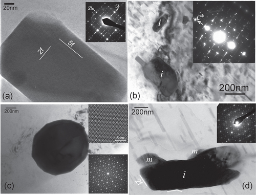
Figure 2. (a) An icosahedral phase particle in a Mg-4.2Zn-0.8Y (at%) alloy extruded at 400 °C, solutionized at 400 °C and aged at 200 °C, and deformed at room temperature. An FFT pattern in (b) shows it to be in a twofold zone axis orientation while the matrix is along a axis. (c) A Fourier filtered lattice image from a region marked in (a), showing a set of matching prismatic planes and fivefold planes corresponding to reciprocal spots {422222} and {311111} (marked ‘1’ and ‘2’, respectively, in (b)) along the fivefold reciprocal vector.
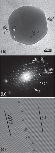
Figure 3. A typical twofold symmetry diffraction pattern from an icosahedral phase in a Mg–Zn–Y alloy. Fivefold and twofold reciprocal vectors are marked.
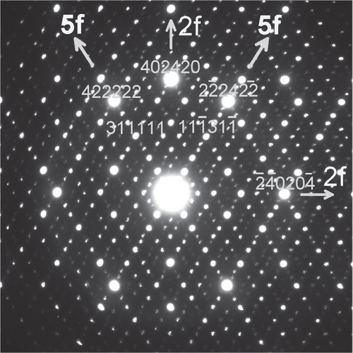
Figure 4. (a) An i-phase particle oriented along a twofold axis in a Mg-6Zn-1Ho (at%) alloy extruded at 230 °C. A diffraction pattern is shown in (b). Matrix (0002) diffraction spots are also observed in the diffraction pattern. Two prominent diffraction spots {422222} and {311111} along a fivefold vector are marked 1 and 2, respectively. Two Fourier filtered images from an area marked in (a) are shown in (c) and (d). In (c) the matrix (0002) and matching i-phase {422222} spot is used for inverse FFT, while in (d) the matrix (0001) and two fivefold vector spots {422222} and {311111} are used for inverse FFT.
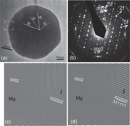
Figure 5. A multibeam transmission electron microscopy (TEM) micrograph showing icosahedral phase grown on W-phase in α-Mg matrix of Mg-2.5Zn-0.5Y (at%) alloy solutionized at 460 °C followed by annealing at 400 °C. The composite electron diffraction pattern (inset) gives the zone axis orientation of the three phases, the icosahedral phase in the twofold zone axis, the W-phase in the [111] zone axis and the α-Mg phase in the zone axis.
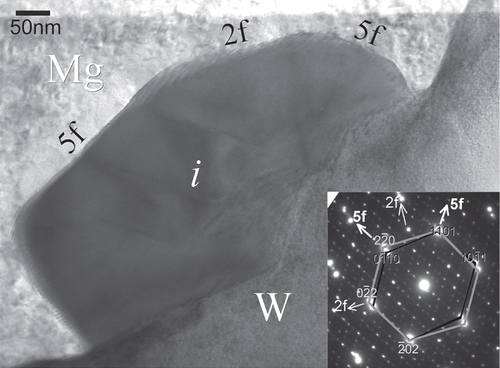
Figure 6. Precipitates in a Mg-6at%Zn-1at%Y alloy solutionized at 440 °C, extruded at 380 °C and aged at 150 °C. (a) A bright field micrograph along a zone axis showing rod-like
precipitates, i-phase particles and Mg4
phase growing on the i-phase. (b) A lattice image along the hexagonal axis of a matrix grain showing
precipitate rods viewed head on. The inset shows the corresponding diffraction pattern.
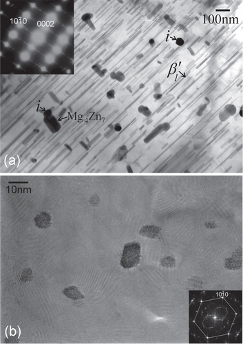
Figure 7. Layered structure of the and Mg4
phases and an intermixing of the two. (a), (b) The structure of the
phase represented as stacking of layers of Mg and Zn atoms along [0001] axis (a) and a
axis (b). An icosahedral unit in (a) is highlighted. Pentagonal arrangements, which make icosahedral units, are observed in (b). Centers of these pentagons are arranged as rhombuses. (c) Structure of the Mg4
phase viewed along the unique monoclinic axis [010]. It is represented as stacking of layers with pentagonal coordinations, making icosahedra. The coordinations are similar to those in the
structure along
axis in (b), except for a hexagonal unit in which zinc atoms are concentrated. The hexagonal unit can be further decomposed into a thick and two thin tiles, as shown in the upper hexagon. (d) A high resolution TEM micrograph of a rod-shaped
precipitates viewed along its long axis. Structure of
phase on the left and Mg4
phase on the right can be identified, as outlined. Regions of zinc concentration are marked with circles.
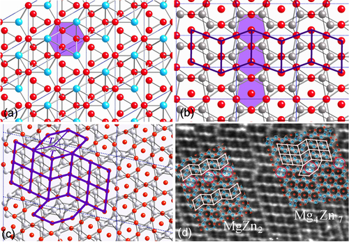
Figure 8. Intergrowth of icosahedral (i) and a precipitate in α-Mg matrix in Mg-2.5Zn-0.5Y (at%) solutionized at 460 °C and a double annealed at 250 °C and 400 °C. The inset shows an FFT, in which horizontal streaks are arranged quasiperiodically while the vertical streaks have the periodicity of basal planes of α-Mg phase and
precipitated phases.
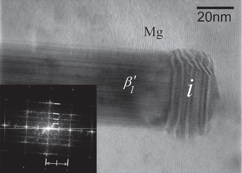
Figure 9. Calculated and experimental increments in yield strength plotted against experimentally determined values of
precipitate diameters d and precipitate spacing on the basal planes in T6 and T8 treated (a) Mg–Zn and (b) Mg–Zn–Y alloys given in [Citation48, Citation49].
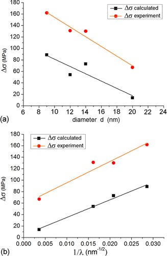
Figure 10. DSC traces of heating and cooling runs of Mg-6Zn-1Y (at%) alloy after solutionizing at 480 °C for 24 h.
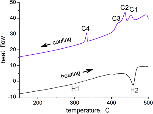
Figure 11. Microstructure of a Mg-6at%Zn-1at%Y chill cast alloy, solutionized at 480 °C and extruded at 440 °C. Two of the large particles of cubic W-phase are marked with arrowheads.
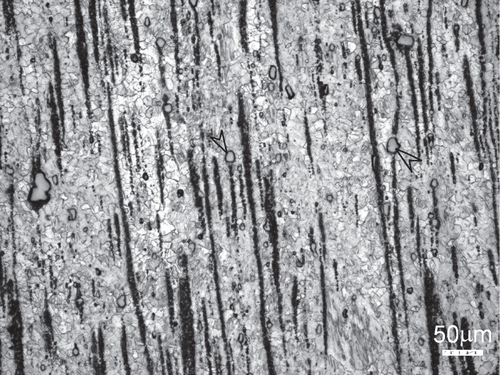
Figure 12. Microstructure of Mg-6at%Zn-1at%Y chill cast alloy, solutionized and extruded at 440 °C. (a) W-phase with i-phase at the interface. In the inset diffraction pattern, i-phase and W-phase diffraction spots are observed. The W-phase is in the [100] zone axis orientation. Icosahedral twofold (2f) and fivefold (5f) reciprocal directions are marked. (b) Microstructure after ageing at 150 °C for 48 h; i-phase particles at grain boundaries are marked with arrowheads. (c) precipitates and i-phase particles are observed in a grain oriented along a
zone axis.
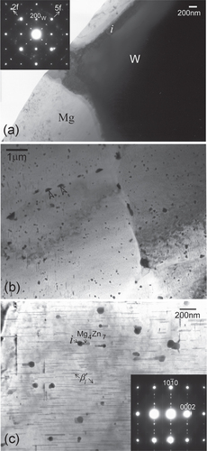
Figure 13. Stress–strain curves in (a) tension and (b) compression of chill-cast, solutionized and extruded Mg-6at%Zn-1at%Y alloy in as-extruded condition and after ageing at 150 °C for 48 h.
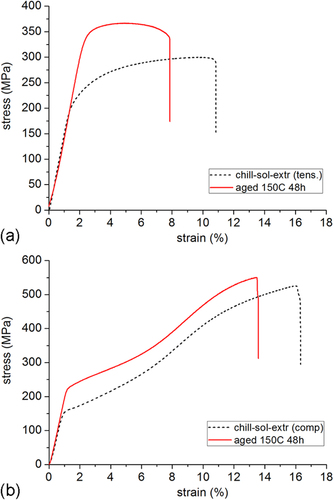
Figure 14. Bright field TEM micrographs showing microstructures of extruded Mg–Zn–Y alloys produced by chill casting. Fine micron level grain sizes are observed. The black particles are the dispersed i-phase. (a) Mg-6Zn-1Y alloy extruded at 250 °C. (b)–(d) Mg-3Zn-0.5Y alloy extruded at (b) 300 °C, (c) 250 °C and (d) 300 °C. Fine nano-sized precipitates in the matrix are clearly observed in the higher magnification micrograph of (d).
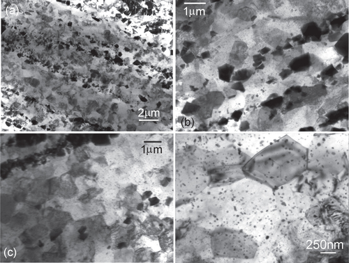
Table 1. Extrusion temperatures and the corresponding grain size, tensile and compressive yield strengths (YS), and tensile elongations of the two alloys Mg-6Zn-1Y and Mg-3Zn-0.5Y (at%) which were chill cast and extruded, and then aged.
Figure 15. (a), (b) Inverse pole figure maps and (c), (d) the corresponding inverse pole figures obtained by EBSD for the alloys Mg-6Zn-1Y extruded at 300 °C (a), (c) and Mg-3Zn-0.5Y alloy extruded at 260 °C (b), (d). Reproduced in part from [Citation52] with permission from Elsevier.
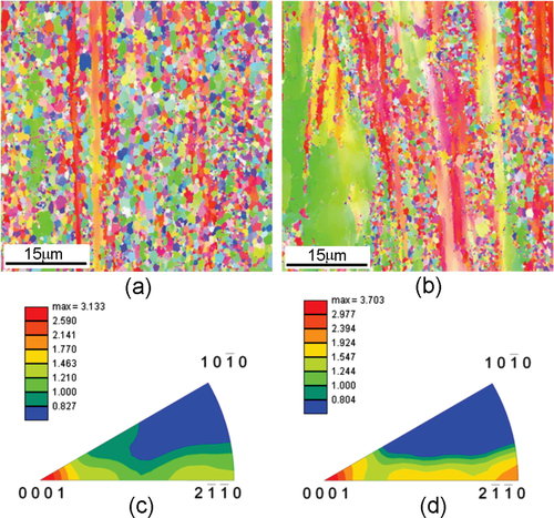
Figure 16. Bright field TEM micrographs from Mg-6Zn-1Y alloy chill cast and extruded at 250 °C. (a) i-phase particles dispersed along the extrusion direction. The inset shows a fivefold diffraction pattern from one of the particles. A ring of spots showing the fivefold symmetry are marked by dots. (b) Matrix grains in between i-phase particles marked ‘i’. (c) An i-phase particle marked by an arrow and its inset diffraction pattern along a twofold zone axis. An adjacent matrix grain in dark contrast is marked ‘M.’ This matrix grain is along a zone axis. Fine nano-sized precipitates are observed in all the micrographs.
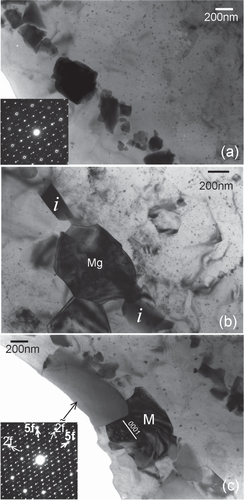
Figure 17. High resolution micrographs showing the interface between the i-phase and the matrix grain M in figure (c). (a) i-phase grain in a twofold zone axis orientation. The inset shows an FFT pattern, on which the twofold (2f) and fivefold (5f) reciprocal directions are marked. (b) A tilt away brings the grain M into a zone axis. One of the fivefold planes of the i-phase is still parallel to the beam, such that 5f
prismatic plane (as observed in the inset FFT pattern). (c) Stacking faults and slip are observed on basal planes in grain M, giving rise to streaking along
reciprocal direction in the inset FFT.
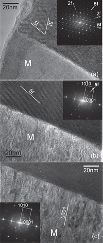
Figure 18. Engineering stress-strain plots for tensile and compression tests of alloys (a) Mg-6at%Zn-1at%Y and (b) Mg-3at%Zn-0.5at%Y, each extruded at three different temperatures.
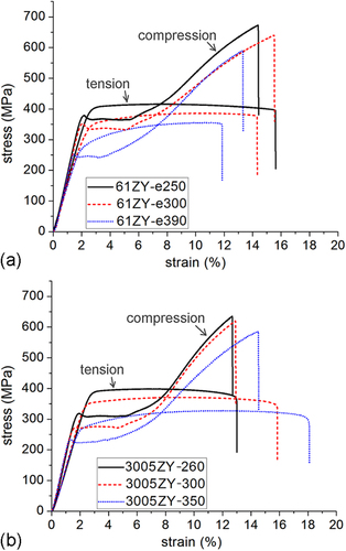
Figure 19. Hall–Petch plot of high strength Mg–Zn–Y alloys described here. ‘T’ represents yield strength in tension and ‘C’ represents compression. Data ‘P’ of powder metallurgy alloy is from [Citation17]. Three regions of grain size-strength are delineated as I, II and III. ’Solut. & extr.’ stands for solutionized and extruded Mg-6at%Zn-1at%Y alloy.
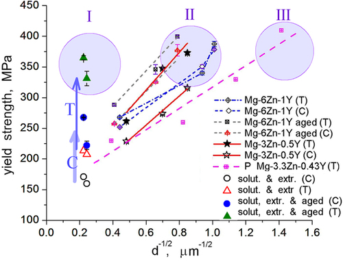
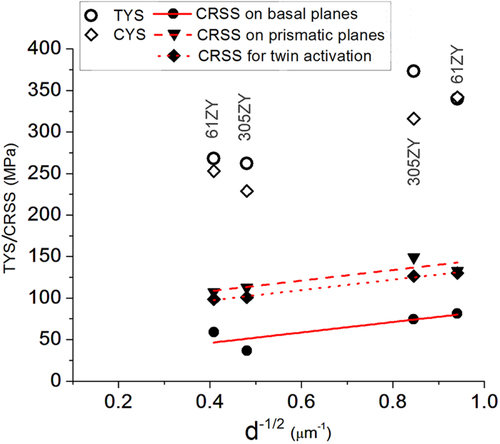
Figure 20. CRSS on basal and prismatic planes calculated from tensile yield strength, and for {} twinning calculated from compressive yield strength, for Mg-6Zn-1Y (61ZY) alloy extruded at 300 °C and 390 °C and Mg-3Zn-0.5Y (305ZY) alloy extruded at 260 °C and 350 °C.