Figures & data
Figure 1 Magnetoconductance ratio, ΔI/I in an ITO/Alq3 (≈100 nm)/Ca device measured at different constant voltages (the approximate current levels are also given) and at room temperature. The molecular structure of Alq3 and current–voltage characteristics of the device are shown as insets.
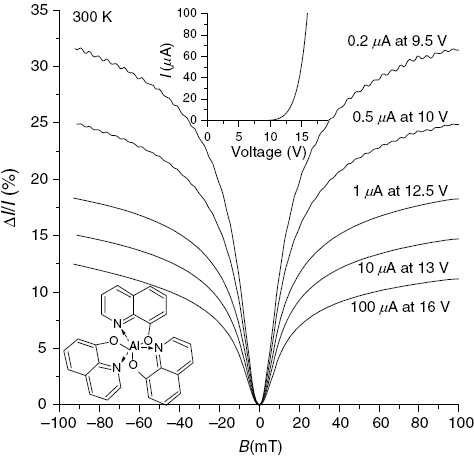
Figure 2 Magnetic field effect (MFE) on current (bold lines) and EL (thin lines) in a PEDOT/Alq3 (≈100 nm)/Ca device measured at several different constant voltages at room temperature. The current–voltage characteristics of the device is shown as an inset.
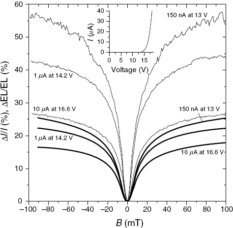
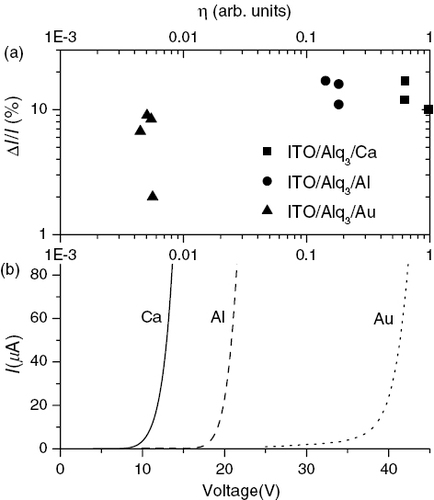
Figure 3 (a) Magnetoconductance ratio, ΔI/I at B=100 mT in several ITO/Alq3 (≈100 nm)/cathode devices with Ca, Al, or Au as the cathode as a function of the exciton/carrier ratio η. For each device, measurements at several different constant applied voltages resulting in a current between ≈1 μA and ≈100 μA are shown. (b) Current–voltage (I–V) characteristics of the devices.