Figures & data
Figure 1. Baseline intraoral photos.
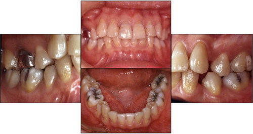
Figure 2. Radiographic images of the mandibular left TMJ at ICP before treatment (top-left), at rest position (top-middle), and at opening position (top-right). The condyle appeared to be displaced posteriorly at ICP and not traveled enough anteriorly at the jaw opening position. No baseline radiographs of the right TMJ are available, due to development failures. Baseline MKG recordings of habitual mandibular movement are shown (bottom). Dyskinesia (arrows) was observed during jaw opening in Scan 1 (bottom-left). The mandible moved anteriorly during closing, arrived at the mid-lingual surface of the maxillary incisor, and slid into ICP. The velocity of jaw movements was recorded and shown in Scan 2 (bottom-right). Bradykinesia was observed when the jaw opened. The velocity of jaw closing movement was normal.
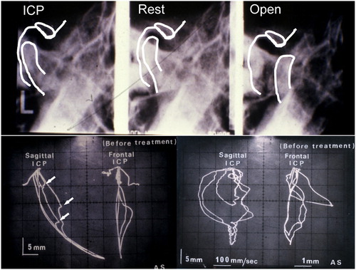
Figure 3. The three-dimensional jaw movement from rest position before treatment (left) and post muscle relaxation by TENS (middle). The mandible positioned approximately 0·6 mm anteriorly, 0·4 mm laterally, and 4·5 mm vertically from rest position after muscle relaxation. The position relationship between rest, MCP, and ICP after muscle relaxation by TENS is shown (right). ICP was located approximately 1 mm posterior to, 3·5 mm above, and 2 mm lateral to MCP.
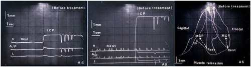
Figure 4. Bite registration was taken at MTCP and mounted in Terminus Articulator. Posterior occlusal discrepancy of 2–3 mm is obvious at MTCP.
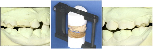
Figure 5. Fabricated CMO appliance on the mandible cast model had anatomical occlusal morphology (top-left). Jaw movements were recorded using MKG K5 after use of the CMO appliance for 1 month. Jaw open–close movements were smooth (bottom-left), and velocity of the movements was significantly improved (bottom-right). However, ICP appeared not yet stable (bottom-right). The recording of three-dimensional jaw movement from rest position shows that the mandible travels approximately 1·5 mm vertically, 1 mm anteriorly, and 0·2 mm laterally at the incisal position.
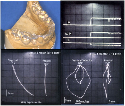
Figure 6. Posterior onlays were fabricated and seated using Panavia EX (top). Jaw movements were recorded using MKG K5 (bottom). Smooth movement to ICP with undisrupted velocity was observed.
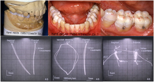
Figure 7. Intraoral photos taken at the 7-year follow-up. No substantial wear was noted on the resin-only restorations.
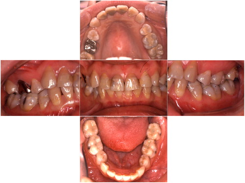
Figure 8. Jaw movements were recorded by the K6 diagnostic system at the 7-year follow-up. Mandibular movements were smooth (left). Bilateral surface EMG recordings were performed using an EM-2. The patient was instructed to clench at ICP and then bite cotton rolls on posterior teeth (right).
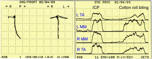
Figure 9. Radiographic images of TMJs at the 7-year follow-up. The right TMJ at ICP (top-left) and at jaw open position (top-right). The left condyle at ICP (bottom-right) and at jaw open position (bottom-left). Both condyles traveled enough anteriorly during jaw opening.
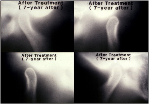
Figure 10. Intraoral photos taken at the 23-year follow-up.
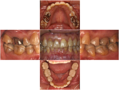
Figure 11. Jaw movements were recorded by the K7 computerized mandibular scanner at the 23-year follow-up. Mandibular movements were smooth (upper-left). Velocity of movements was not consistent, but was acceptable (upper-right). Jaw movements during gum chewing were recorded: left side chewing (bottom-left) and right side chewing (bottom-right).
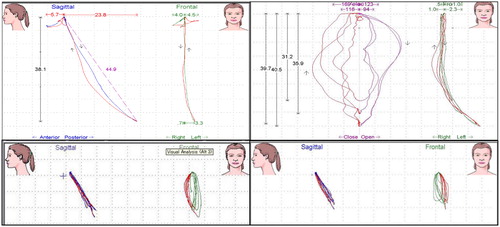
Figure 12. Bilateral surface EMG recordings were performed using EM-2 at the 23-year follow-up. The patient was instructed to clench at ICP and then bite cotton rolls on posterior teeth.
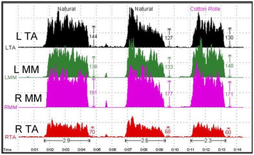
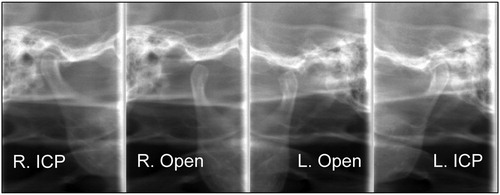
Figure 13. Radiographic images of TMJs at the 23-year follow-up. The right TMJ at ICP (far-left) and at jaw open position (center-left). The left condyle at ICP (far-right) and at jaw open position (center-right). Both condyles traveled enough anteriorly during jaw opening.