Review of Bi2O3 based glasses for electronics and related applications
T Maeder*
Laboratoire de Production Microtechnique (LPM), École Polytechnique Fédérale de Lausanne (EPFL), BM 1·136, Station 17, CH-1015Lausanne, SwitzerlandCorrespondence[email protected]
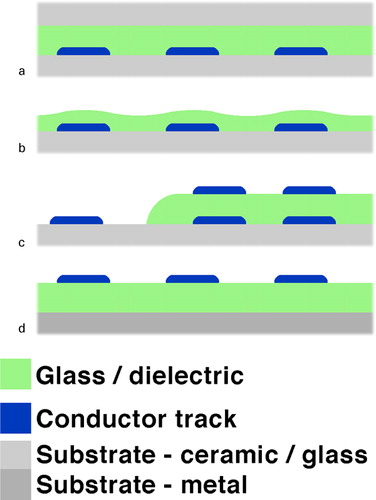
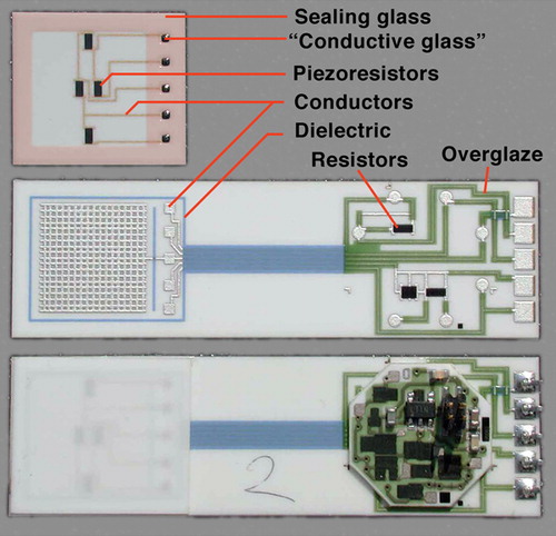
Figure 1. Example TF circuit, piezoresistive pressure sensorCitation27, showing typical involved materials: reddish tint added to sealing glass to enhance visibility; ‘conductive glass’ seal = low firing TFR composition
Table 1. Representative compositions (cation-%) of low melting lead based glasses [Temperatures = melting points (eutectics) or processing temperatures (others)]
Table 5. Qualitative composition (+++ = high, ++ = medium, + = low, ? = very low or absent) of commercial TF inks (Tf = firing temperature): dielectricsCitation167 (compared with LTCC),Citation168–Citation170 conductorCitation164 and resistor.Citation85 Boron most likely present in all these compositions, but not always detectable by the analysis methods – mentioned where explicitly formulated/detected
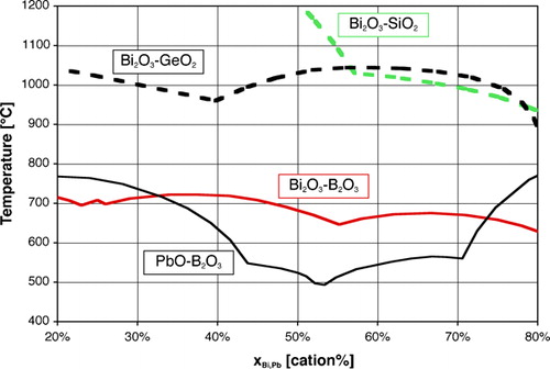
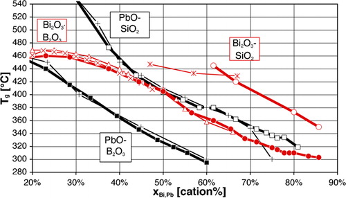
Figure 2. Liquidus temperatures of binary systems, redrawn from phase diagrams Bi2O3–SiO2,Citation281 Bi2O3–GeO2 (PDC-2359), Bi2O3–B2O3 (PDC-323) and PbO–B2O3 (PDC-282)
Figure 3. Glass transition temperatures Tg of binary systems according to George et al.Citation248 (heavy lines), compared with other works (×: Ref. 317; Δ: Ref. 318; +: Ref. 141; *: Ref. 319)
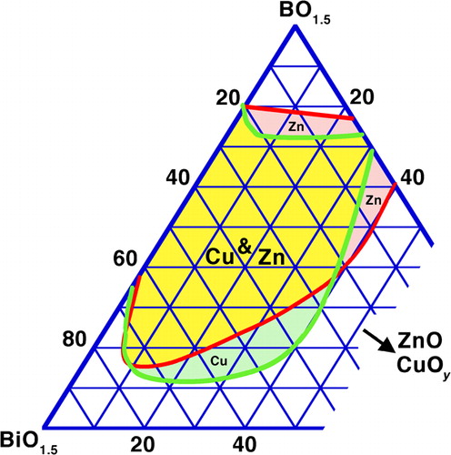
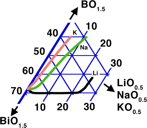
Table 12. Glass-forming range of Bi2O3 and PbO/SnOFootnote† binary systems with networkforming oxides, with quenching index Q and crucibleFootnote‡ indicated as subscript
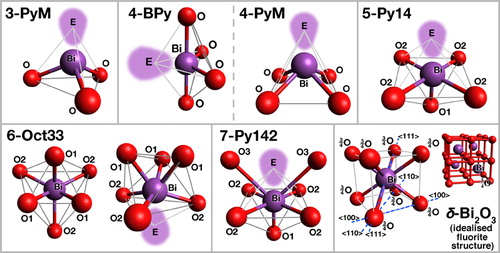
Figure 6. Some oxygen coordination shells around Bi observed in crystalline oxides (see section on ‘Coordination of bismuth in crystalline oxides’ in Supplementary Material 1 http://dx.doi.org/10.1179/1743280412Y.0000000010.S1 and ): E = Bi3+ lone pair electrons
Table 14. Description of oxygen coordination shells around Bi observed in crystalline oxides (see section on ‘Coordination of bismuth in crystalline oxides’ in Supplementary Material 1 http://dx.doi.org/10.1179/1743280412Y.0000000010.S1 and ) (E stands for Bi3+ lone pair electrons)
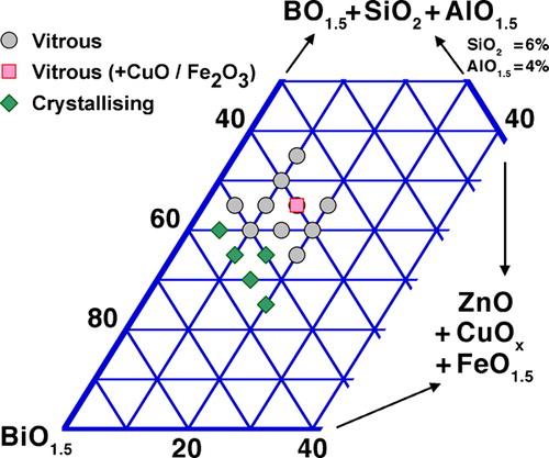
Figure 9. Results, in cation-%, of our experiments on stability of Bi2O3 based glasses in TF firing cycles (belt oven, 45 min total time with 10 min at peak, 400–700°C)
Table 19. Composite sealing glasses (compositions: see )
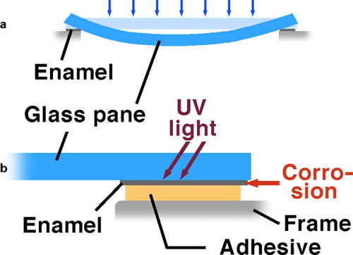
Figure 10. Application of enamel to automotive glass, as a antistick layer during forming and b adhesive protection layer (redrawn from SakoskeCitation47)
Table 21. Advantages and issues of Bi in conductors and component metallisations.
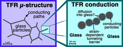
Figure 11. Microstructure and conduction mechanism of TFRsCitation1
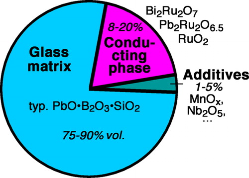
Figure 12. Typical composition (without temporary vehicle/binder) of TFRs with lead borosilicate glass matrixCitation1
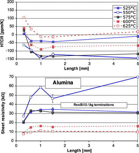
Figure 13. Sheet resistivity at 25°C and temperature coefficient (HTCR, 25–100°C), versus length and firing temperature, of experimental TFRs fired on Al2O3 with Ag terminationsCitation1
Prudenziati M, Morten B, Cilloni F, Ruffi G, Sacchi M: ‘Interactions between alumina and high lead glasses for hybrid components’, J. Appl. Phys., 1989, 65, (1), 146–153.
Prudenziati M, Morten B, Forti B, Gualtieri AF, Dilliway GM: ‘Devitrification kinetics of high lead glass for hybrid microelectronics’, Int. J. Inorg. Mater., 2001, 3, (7), 667–674.
Hoffman LC: ‘Metallizing compositions containing critical proportions of metal (Pt–Au or Pd–Au) and a specific high density frit’, Patent US3440062, 1969.
Zdaniewski W, Silverman L: ‘Effect of localized redox equilibria on adhesion between gold and thick-film dielectrics’, J. Mater. Sci., 1990, 25, (7), 3155–3158.
Geodakyan D, Petrosyan B, Stepanyan S, Geodakyan K: ‘Investigation of the possibility of replacing high-lead glasses in fusible glass solders by less toxic glasses’, Glass Ceram., 2009, 66, (11–12), 381–384.
Shimbo M, Tai S, Tanzawa K: ‘Glass formation range, acid resistivity, and surface charge density of ZnO–B2O3–SiO2 passivation glass containing Al2O3’, J. Am. Ceram. Soc., 1986, 69, (1), 23–26.
Shimbo M, Furukawa K: ‘Physical and electrical properties of acid resistive zinc–lead borosilicate passivation glass’, J. Ceram. Soc. Jpn Int Edn, 1988, 96, 201–205.
Fredericci C, Yoshimura HN, Molisani AL, Fellegara H: ‘Effect of TiO2 addition on the chemical durability of Bi2O3–SiO2–ZnO–B2O3 glass system’, J. Non-Cryst. Solids, 2008, 354, (42–44), 8592–8598.
Hrovat M, Maeder T, Jacq C, Holc J, Bernard J: ‘Subsolidus phase equilibria in the PbO-poor part of the TiO2–PbO–SiO2 system and its application in low-temperature thick-film dielectrics’, J. Mater. Res., 2006, 21, (12), 3210–3214.
Jones WK, Liu Y, Larsen B, Wang P, Zampino M: ‘Chemical, structural and mechanical properties of the LTCC tapes’, Proc. Int. Symp. on ‘Microelectronics’, Boston, MA, USA, September 2000, SPIE, 669–674.
Bienert C, Roosen A: ‘Characterization of material behavior of low temperature cofired ceramics at elevated temperatures’, J. Eur. Ceram. Soc., 2010, 30, (2), 369–374.
Birol H, Maeder T, Ryser P: ‘Influence of processing and conduction materials on properties of co-fired resistors in LTCC structures’, J. Eur. Ceram. Soc., 2006, 26, (10–11), 1937–1941.
Fu SL, Hsi CS, Kang CY, Chin WH, Hsieh TY: ‘Influences of additives on the electrical properties of lead-free thick film resistors’, Proc. XXIX Int. Conf. of IMAPS Poland, Koszalin, Poland, September 2005, IMAPS, 19–24.
Rane SB, Prudenziati M, Morten B: ‘Microstructure and electrical properties of perovskite ruthenate-based lead-free thick film resistors on alumina and LTCC’, Proc. XXVIII Int. Conf. of IMAPS Poland Chapter, Wroclaw Poland, Setember 2004, IMAPS, 362–365.
Kiełbasiński K, Młożniak A, Jakubowska M: ‘High ohm eco-friendly resistors in thick film technology’, Proc. XXXII Int. Conf. of IMAPS Poland Chapter, Pułtusk, Poland, September 2008, IMAPS, B09.
Prudenziati M, Morten B, Rane SB: ‘Perovskite ruthenate based lead free thick film resistors’, Proc. Eur. Microelectronics and Packaging Symp., Prague, Czech, June 2004 , IMAPS, 277–282.
Boyd DC, Danielson PS, Thompson DA, Velez M, Reis ST, Brow RK: ‘Glass’, in ‘Kirk–Othmer encyclopedia of chemical technology’, 5th edn, 565–626; 2005, Hoboken, Wiley.
Leveaux M, Crevit N, Lips K, Schepers B, Aerts A, Verboom E: ‘Nuovi orizzonti nella smaltatura dell’alluminio [New horizons in the enamelling of aluminium]’, Smalto Porcellanato, 2002, 44, (2).
Monzio Compagnoni A, Ferraro A: ‘Smaltatura dell’aluminio ad alto tenore di magnesio [enamelling of aluminium with high magnesium content]’, Smalto Porcellanato, 2005, 47, (2).
Monzio Compagnoni A: ‘Riduzione o eliminazione del vanadio nello smalto per alluminio [Reduction or elimination of vanadium in enamels for aluminium]’, Smalto Porcellanato, 2006, 48, (1).
Masuda H, Kimura R, Sakamoto N, Morinaga K: ‘Properties and structure of glasses in the system BaO–B2O3–ZnO’, J. Jpn Inst. Met., 1999, 63, (3), 6284–6288.
Fukaya M, Matsuo T, Nishigaki S, Higuchi C: ‘Highly reliable and lead (Pb) free thick film resistor paste system for low thermal expansion LTCC application’, Proc. 1997 Int. Symp. on ‘Microelectronics’, Philadelphia, PA, USA, October 1997, IMAPS, 65–71.
Hasegawa S, Onishi H, Kanai M, Kamimoto T: ‘Bismuth glass composition, and magnetic head and plasma display panel including the same as sealing member’, Patent US2005 0181927, 2005.
Hwang SJ, Lee SW, Kim HS: ‘Sintering behavior of silver conductive thick film with frit in information display’, J. Electroceram., 2008, 23, (2–4), 351–355.
Busana MG, Prudenziati M, Hormadaly J: ‘Microstructure development and electrical properties of RuO2 based lead free thick film resistors’, J. Mater. Sci., 2006, 17, (11), 951–962.
Jeon SJ, Koo SM, Hwang SA: ‘Optimization of lead- and cadmium-free front contact silver paste formulation to achieve high fill factors for industrial screen-printed Si solar cells’, Solar Energy Mater. Solar Cells, 2009, 93, (6–7), 1103–1109.
Nachmansohn B: ‘Verre de soudure à dévitrification sans plomb ni autres matériaux toxiques [Devitrifying solder glass without lead or other toxic materials]’, Patent FR2794120, 2000.
Singh N, Singh K: ‘Comparative study of lead borate and bismuth lead borate glass systems as gamma-radiation shielding materials’, Nucl. Instrum. Methods Phys. Res. B, 2004, 225B, (3), 305–309.
Saisudha MB, Koteswara Rao KSR, Bhat HL, Ramakrishna J: ‘The fluorescence of Nd3+ in lead borate and bismuth borate glasses with large stimulated emission cross section’, J. Appl. Phys., 1996, 80, (9), 4845–4853.
Dimitrov V, Komatsu T: ‘Average single bond strength and optical basicity of Bi2O3–B2O3 and Sb2O3–B2O3 glasses’, J. Non-Cryst. Solids, 2010, 356, (4–5), 258–262.
George HB, Vira C, Stehle C, Meyer J, Evers S, Hogan D, Feller S, Affatigato M: ‘A structural analysis of the physical properties of bismuth and lead based glasses’, Phys. Chem. Glasses, 1999, 40, (6), 326–332.
Sharma G, Thind KS, Monika, Singh H, Manupriya, Gerward L: ‘Optical properties of heavy metal oxide glasses before and after γ-irradiation’, Phys. Status Solidi A, 2007, 204A, (2), 591–601.
El Sayed M, Saddeek YB, Shaaban ER: ‘Structural and optical properties of lithium borobismuthate glasses’, J. Phys. Chem. Solids, 2008, 69, (9), 2281–2287.
Saddeek YB, Shaaban ER, El Sayed M, Hesham MM: ‘Spectroscopic properties, electronic polarizability, and optical basicity of Bi2O3–Li2O–B2O3 glasses’, Physica B, 2008, 403, (13–16), 2399–2407.
Subhadra M, Kistaiah P: ‘Characterization and optical absorption studies of VO2+:Li2O–K2O–Bi2O3–B2O3 glass system’, J. Alloys Compd, 2010, 505, 634–639.
Rani S, Sanghi S, Anshu A, Agarwal A, Kishore N, Seth VP: ‘Effect of ZnO/CdO on the structure and electrical conductivity in Li2O·MO·Bi2O3·B2O3 glasses (M = Zn, Cd)’, J. Phys. Chem. Solids, 2008, 69, (7), 1855–1860.
Al Hajry A, Soliman AA, El Desoky MM: ‘Electrical and thermal properties of semiconducting Fe2O3–Bi2O3–Na2B4O7 glasses’, Thermochim. Acta, 2005, 427, (1–2), 181–186.
El Desoky MM, Tashtoush NM, Habib H: ‘Characterization and electrical properties of semiconducting Fe2O3–Bi2O3–K2B4O7 glasses’, J. Mater. Sci., 2005, 16, (8), 533–539.
Kargin YF, Ivicheva SN, Shvorneva LI, Komova MG, Krut’ko VA: ‘Phase relations in the CaO–Bi2O3–B2O3 system in the subsolidus region’, Russ. J. Inorg. Chem, 2008, 53, (9), 1512–1516.
Kargin YF, Ivicheva SN, Komova MG, Krut’ko VA: ‘Phase relations in the solidus region of the SrO–Bi2O3–B2O3 system’, Russ. J. Inorg. Chem, 2008, 53, (3), 474–478.
Janakirama-Rao BV: ‘Unusual properties and structure of glasses in the systems Bi2O3–B2O3–SrO; Bi2O3–B2O3–BaO; Bi2O3–B2O3–ZnO and Bi2O3–B2O3–PbO’, Proc. 7th Int. Cong. on ‘Glass’, Brussels, Belgium, June 1965, 104.101–104.106.
Sindhu S, Sanghi S, Agarwal A, Seth VP, Kishore N: ‘Effect of Bi2O3 content on the optical band gap, density and electrical conductivity of MO·Bi2O3·B2O3 (M = Ba, Sr) glasses’, Mater. Chem. Phys., 2005, 90, (1), 83–89.
Qiao W, Chen P: ‘Study on the properties of Bi2O3–B2O3–BaO lead free glass using in the electronic pastes’, Glass Phys. Chem., 2010, 36, (3), 1956–1960.
Watanabe T, Muratsubaki K, Benino Y, Saitoh H, Komatsu T: ‘Hardness and elastic properties of Bi2O3 based glasses’, J. Mater. Sci., 2001, 36, (10), 2427–2433.
Hamezan M, Sidek H, Zaidan A, Kaida K, Zainal A: ‘Elastic constants and thermal properties of lead bismuth borate glasses’, J. Appl. Sci., 2006, 6, (4), 943–949.
Aziz S, Hamezan A, Zaidan A, Zainal A, Zainal A, Shaari A, Senin H: ‘Ultrasonic and thermal properties of borate and phosphate glasses containing bismuth and lead’, AIP Conf. Proc., 2007, 909, 197–209.
Peng M, Cordt Z, Wondraczek L: ‘Origin of broad NIR photoluminescence in bismuthate glass and Bi-doped glasses at room temperature’, J. Phys.: Condensed Matter, 2009, 21, (28), 285106.
Saritha D, Markandeya Y, Salagram M, Vithal M, Singh AK, Bhikshamaiah G: ‘Effect of Bi2O3 on physical, optical and structural studies of ZnO–Bi2O3–B2O3 glasses’, J. Non-Cryst. Solids, 2008, 354, (52–54), 5573–5579.
Kim BS, Lim ES, Lee JH, Kim JJ: ‘Effect of structure change on thermal and dielectric characteristics in low temperature firing Bi2O3–B2O3–ZnO glasses’, J. Mater. Sci., 2007, 42, (12), 4260–4264.
Dyamant I, Itzhak D, Hormadaly J: ‘Thermal properties and glass formation in the SiO2–B2O3–Bi2O3–ZnO quaternary system’, J. Non-Cryst. Solids, 2005, 351, 3503–3507.
Shuster NS, Novruzova FA, Zeinalova CLK, Zargarova MI: ‘Glass forming and physico-chemical properties of glasses in the system CuO−Bi2O3−B2O3’, Fizika i Chimija Stekla, 1990, 16, (2), 197–200.
Simon S, Eniu D: ‘Spectroscopic characterisation of local structure in Y2O3–B2O3–Bi2O3 glasses doped with gadolinium’, J. Mater. Sci., 2007, 42, (15), 5949–5953.
Pascuta P, Borodi G, Culea E: ‘Influence of europium ions on structure and crystallization properties of bismuth borate glasses and glass ceramics’, J. Non-Cryst. Solids, 2008, 354, (52–54), 5475–5479.
Pascuta P, Pop L, Rada S, Bosca M, Culea E: ‘The local structure of bismuth borate glasses doped with europium ions evidenced by FT-IR spectroscopy’, J. Mater. Sci., 2008, 19, (5), 424–428.
Pascuta P, Rada S, Borodi G, Bosca M, Pop L, Culea E: ‘Influence of europium ions on structure and crystallization properties of bismuth-alumino-borate glasses and glass ceramics’, J. Molec. Struct., 2009, 924–926, 214–220.
Rada S, Culea M, Rada M, Pascuta P, Matles V, Culea E: ‘The double role played by the Gd2O3 in the gadolinium–aluminum–borate–bismuthate quaternary glass forming tendency. GdBO3 crystalline phase’, J. Molec. Struct., 2009, 937, 70–74.
Saddeek YB, Yahia IS, Aly KA, Dobrowolsky W: ‘Spectroscopic, mechanical and magnetic characterization of some bismuth borate glasses containing gadolinium ions’, Solid State Sci., 2010, 12, (8), 1426–1434.
Dai S, Lu L, Xu T, Nie Q, Shen X, Wang X: ‘Optical properties of and concentration quenching in Bi2O3–B2O3–Ga2O3 glasses’, J. Non-Cryst. Solids, 2007, 353, (28), 2744–2749.
Kim BS, Lim ES, Lee JH, Kim JJ: ‘Effect of Bi2O3 content on sintering and crystallization behavior of low-temperature firing Bi2O3–B2O3–SiO2 glasses’, J. Eur. Ceram. Soc., 2007, 27, (2–3), 819–824.
Zhang Y, Yang Y, Zheng J, Hua W, Chen G: ‘Effects of oxidizing additives on optical properties of Bi2O3–B2O3–SiO2 glasses’, J. Am. Ceram. Soc., 2008, 91, (10), 3410–3412.
Gao G, Hu L, Fan H, Wang G, Li K, Feng S, Fan S, Chen H: ‘Effect of Bi2O3 on physical, optical and structural properties of boron silicon bismuthate glasses’, Opt. Mater., 2009, 32, (1), 159–163.
Fei YT, Fan SJ, Sun RY, Ishii M: ‘Study on phase diagram of Bi2O3−SiO2 system for Bridgman growth of Bi4Si3O12 single crystal’, Prog. Cryst. Growth Charact. Mater., 2000, 40, (1–4), 183–188.
Gackowska J, Gazda M, Trzebiatowski K, Kusz B: ‘Structure and electric conductivity of reduced lead–germanate, bismuth–germanate and bismuth–silicate glasses modified with potassium’, J. Non-Cryst. Solids, 2008, 354, (35–39), 4319–4322.
Shi DM, Zhang QY, Yang GF, Jiang ZH: ‘Spectroscopic properties and energy transfer in Ga2O3–Bi2O3–PbO–GeO2 glasses codoped with Tm3+ and Ho3+’, J. Non-Cryst. Solids, 2007, 353, (16–17), 1508–1514.
Yang GF, Shi DM, Zhang QY, Jiang ZH: ‘Spectroscopic properties of Er3+/Yb3+-codoped PbO–Bi2O3–Ga2O3–GeO2 glasses’, J. Fluoresc., 2008, 18, (1), 131–137.
Shi DM, Zhao YG, Qian Q, Chen DD, Zhang QY: ‘Role of PbO substitution by Bi2O3 on 1·47 μm luminescence properties of Tm3+/Tb3+-doped Bi2O3–GeO2–Ga2O3 glass’, J. Alloys Compd, 2010, 499, (1), 126–130.
Ardelean I, Peteanu M, Simon V, Bob C, Filip S: ‘EPR and magnetic susceptibility studies of Cr2O3–Bi2O3–GeO2 glasses’, J. Mater. Sci., 1998, 33, (2), 357–362.
Pascuta P, Pop L, Rada S, Bosca M, Culea E: ‘The local structure of bismuth germanate glasses and glass ceramics doped with europium ions evidenced by FT IR spectroscopy’, Vibrat. Spectrosc., 2008, 48, (2), 281–284.
Feltz A, Morr A: ‘Redox reactions in condensed oxide systems. III. Glass formation and properties in the Bi2O3−P2O5 system’, J. Non-Cryst. Solids, 1985, 74, (2–3), 313–324.
El Adawy AA: ‘Effect of annealing temperature on the elastic properties of bismuth phosphate glasses’, J. Mater. Sci. Letters, 1996, 15, (23), 2061–2064.
Moguš Milanković A, Šantič A, Ličina V, Day DE: ‘Dielectric behavior and impedance spectroscopy of bismuth iron phosphate glasses’, J. Non-Cryst. Solids, 2005, 351, 3235–3245.
Rani S, Sanghi S, Agarwal A, Ahlawat N: ‘Influence of Bi2O3 on optical properties and structure of bismuth lithium phosphate glasses’, J. Alloys Compd, 2009, 477, 504–509.
Na YH, Kim NJ, Im SH, Cha JM, Ryu BK: ‘Effect of Bi2O3 on structure and properties of zinc bismuth phosphate glass’, J. Ceram. Soc. Jpn, 2009, 117, (1371), 1273–1276.
Pöppl L, Szaller Z: ‘Reactions and phases within the TeO2-rich part of the Bi2O3–TeO2 system − the non-equilibrium phase diagram’, J. Therm. Anal. Calorim., 2003, 74, (2), 375–386.
Udovic M, Valant M, Jančar B, Suvorov D: ‘Phase formation and crystal structure determination in the Bi2O3−TiO2−TeO2 system prepared in an oxygen atmosphere’, J. Am. Ceram. Soc., 2006, 89, (11), 3462–3469.
Udovic M, Thomas P, Mirgorodsky A, Durand O, Soulis M, Masson O, Merle Méjean T, Champarnaud Mesjard JC: ‘Thermal characteristics, Raman spectra and structural properties of new tellurite glasses within the Bi2O3–TiO2–TeO2 system’, J. Solid State Chem., 2006, 179, (10), 3252–3259.
Blanchandin S, Thomas P, Marchet P, Champarnaud, JC M, Frit B: ‘New heavy metal oxide glasses: investigations within the TeO2-Nb2O5-Bi2O3 system’, J. Alloys Compd, 2002, 347, 206–212.
Chen Y, Nie Q, Xu T, Dai S, Wang X, Shen X: ‘A study of nonlinear optical properties in Bi2O3–WO3–TeO2 glasses’, J. Non-Cryst. Solids, 2008, 354, 3468–3472.
Ozdanova J, Tichá H, Tichý L: ‘Optical band gap and Raman spectra in some (Bi2O3)x(WO3)y(TeO2)100−x−y and (PbO)x(WO3)y(TeO2)100−x−y glasses’, J. Non-Cryst. Solids, 2009, 354, (45–47), 3468–3472.
Hill CJ, Jha A: ‘Development of novel ternary tellurite glasses for high temperature fiber optic mid-IR chemical sensing’, J. Non-Cryst. Solids, 2007, 353, (13–15), 1372–1376.
Yousef E, Hotzel M, Rüssel C: ‘Effect of ZnO and Bi2O3 addition on linear and non linear optical properties of tellurite glasses’, J. Non-Cryst. Solids, 2007, 353, (4), 333–338.
Iordanova R, Dimitriev Y, Dimitrov V, Kassabov S, Klissurski D: ‘Glass formation and structure in the V2O5–Bi2O3–Fe2O3 glasses’, J. Non-Cryst. Solids, 1996, 204, (2), 141–150.
Iordanova R, Dimitriev Y, Dimitrov V, Kassabov S, Klissurski D: ‘Glass formation and structure in the system MoO3–Bi2O3–Fe2O3’, J. Non-Cryst. Solids, 1998, 231, 227–233.
Iordanova R, Dimitrov V, Dimitriev Y, Klissurski D: ‘Glass formation and structure of glasses in the V2O5–MoO3–Bi2O3 system’, J. Non-Cryst. Solids, 1994, 180, (1), 58–65.
Iordanova R, Lefterova E, Uzunov I, Dimitriev Y, Klissurski D: ‘Non isothermal crystallization kinetics of V2O5−MoO3−Bi2O3 glasses’, J. Therm. Anal. Calorim., 2002, 70, (2), 393–404.
Sun H, Xu S, Dai S, Wen L, Zhang J, Hu L, Jiang Z: ‘Efficient frequency upconversion emission in Er3+-doped novel strontium lead bismuth glass’, J. Non-Cryst. Solids, 2005, 351, (3), 288–292.
Radu A, Baia L, Kiefer W, Simon S: ‘The influence of manganese cations on the structure of lead high bismuthate glasses and glass ceramics’, Vibrat. Spectrosc., 2005, 39, (2), 127–130.
McCloy J, Riley B, Johnson B, Schweiger M, Qiao HA, Carlie N: ‘The predictive power of electronic polarizability for tailoring the refractivity of high-index glasses: optical basicity versus the single oscillator model’, J. Am. Ceram. Soc., 2010, 93, (6), 1650–1662.
Zhou B, Pun EY, Lin H, Yang D, Huang L: ‘Judd–Ofelt analysis, frequency upconversion, and infrared photoluminescence of Ho3+-doped and Ho3+/Yb3+-codoped lead bismuth gallate oxide glasses’, J. Appl. Phys., 2009, 106, (10), 103105.
dos Santos IMG, Martins Moreira RC, de Souza AG, Lebullenger R, Hernandes AC, Leite ER, Paskocimas CA, Longo E: ‘Ceramic crucibles: a new alternative for melting of PbO–BiO1·5–GaO1·5 glasses’, J. Non-Cryst. Solids, 2003, 319, 304–310.
Watanabe T, Nanba T, Miura Y: ‘X-ray and neutron scattering study of the structure of lithium bismuth oxide glass’, J. Non-Cryst. Solids, 2002, 297, (1), 73–83.
Takaishi T, Jin J, Uchino T, Yoko T: ‘Structural study of PbO–B2O3 glasses by X-ray diffraction and 11B MAS NMR techniques’, J. Am. Ceram. Soc., 2000, 83, (10), 2543–2548.
Hayashi A, Nakai M, Tatsumisago M, Minami T, Himei Y, Miura Y, Katada M: ‘Structural investigation of SnO–B2O3 glasses by solid-state NMR and X-ray photoelectron spectroscopy’, J. Non-Cryst. Solids, 2002, 306, (3), 227–237.
Sanz O, Haro Poniatowski E, Gonzalo J, Fernández N, J.M: ‘Influence of the melting conditions of heavy metal oxide glasses containing bismuth oxide on their optical absorption’, J. Non-Cryst. Solids, 2006, 352, (8), 761–768.
Nitta A, Miura T, Komatsu T, Matusita K: ‘Glass formation in the system SiO2–PbO containing transition metal oxides’, J. Am. Ceram. Soc., 1989, 72, (1), 163–165.
Komatsu T, Sato R, Meguro H, Matusita K, Yamashita T: ‘Effect of copper content on glass formation and superconductivity in the Bi–Pb–Sr–Ca–Cu–O system’, J. Mater. Sci., 1991, 26, (3), 683–688.
Holland D, Hannon AC, Smith ME, Johnson CE, Thomas MF, Beesley AM: ‘The role of Sb5+ in the structure of Sb2O3–B2O3 binary glasses – an NMR and Mössbauer spectroscopy study’, Solid State Nucl. Magn. Reson., 2004, 26, (3–4), 172–179.
Sakoske GE: ‘Functional glass coatings (presentation)’, Proc. IMI Int. Workshop on ‘Scientific challenges of new functionalities in glass’, Washington, DC, USA, April 2007, IMI.
Tatsumisago M, Inoue S, Tohge N, Minami T: ‘Dopants in high Tc superconductors from rapidly quenched Bi1·6Pb0·4Ca2Sr2Cu3Ow glasses’, J. Mater. Sci., 1993, 28, (15), 4193–4196.
![Figure 7. [BO4] tetrahedra fraction N4 in boron coordination polyhedra ([BO3] and [BO4]), for Bi2O3–B2O3 glass (○: Ref. 318; +: Ref. 247; □: Ref. 327) and crystallised glass (•: Ref. 318), (ZnO.Bi2O3)–B2O3 glass (Δ: Ref. 355) and PbO–B2O3 glass (×: Ref. 397)](/cms/asset/a4acd27c-48fc-4807-aaa2-2d3c4de5e495/yimr_a_11743737_f0007_b.jpg)