Figures & data
Table 1 Conventional breast cancer prescreening/screening and emerging imaging modalities
Figure 1 Spectrum of absorption from 400 nm to 1,000 nm.
Abbreviation: Hb, hemoglobin.
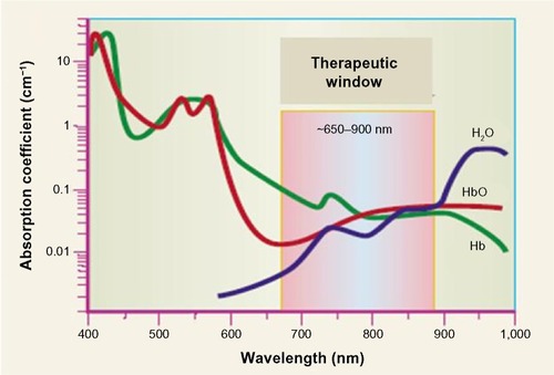
Figure 2 Different hand-held probes developed for early detection of breast cancer, showing their source–detector layouts and the actual device.
Abbreviation: CMOS, complementary metal oxide semiconductor.
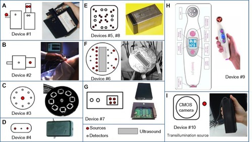
Table 2 Optical imaging devices developed for prescreening or early-stage breast cancer imaging
Figure 3 Setup for breast imaging studies consisting of the breast tissue placed in between two transparent plates.
Abbreviation: NIR, near-infrared.
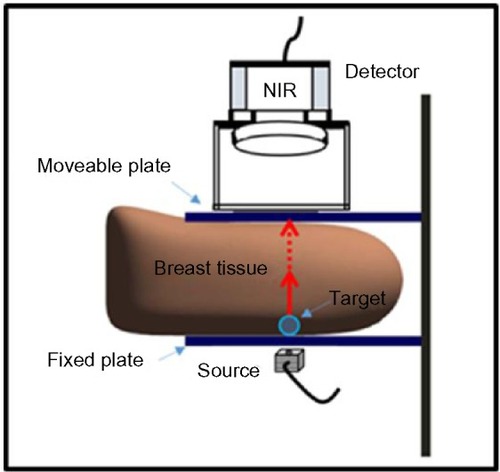
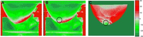
Figure 4 Transmitted NIR optical images of the left breast from subject #1 that were captured at a constant pressure applied on the breast (in all images).
Abbreviation: NIR, near-infrared.
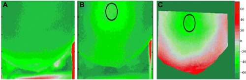
Figure 5 Transmitted NIR optical images of the left breast from subject #2 that were captured at a constant pressure applied on the breast (in all images).
Abbreviation: NIR, near-infrared.