Figures & data
Figure 1 Illustration of different forms of protein formulation fabricated using microfluidics system.
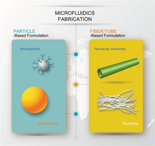
Figure 2 (A) Top: Schematic of formation of nanoparticle via hydrodynamic flow focusing. Bottom: The size distribution of nanoparticles fabricated by different approaches (flow ratio =0.03 and 0.1 refer to ratio of flow rates of PLGA-PEG/water). Reprinted (adapted) with permission from Karnik R, Gu F, Basto P, et al. Microfluidic platform for controlled synthesis of polymeric nanoparticles. Nano Lett. 2008;8(9):2906–2912.Citation25 Copyright (2008) American Chemical Society. (B) (i) Schematic of formation of microfluidic emulsion droplets. Middle: Image of droplets produced and their size distribution. Scale bar is 200 µm. (ii) Images of droplets stored in the device, (iii) collected off-chip, and (iv) forming microparticles via self-assembly after 24 hours. Scale bar is 100 µm. Copyright © 2014. Dove Medical Press. Adapted from Bai S, Debnath S, Gibson K, et al. Biocatalytic self-assembly of nanostructured peptide microparticles using droplet microfluidics. Small. 2014;10(2):285–293.Citation39
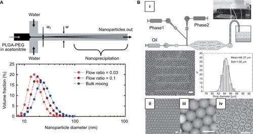
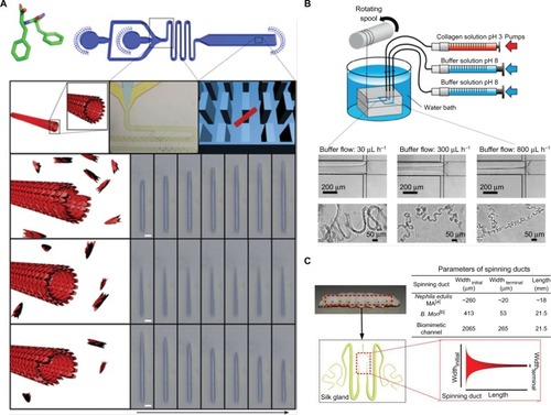
Figure 3 (A) Top: Diphenylalanine monomer and the design of the microfluidic device for nanotube assembly. Bottom: Illustration and imaging of nanotube formation at supercritical, critical, and subcritical monomer concentrations in flow. Scale bar is 5 µm. Adapted from Arnon ZA, Vitalis A, Levin A, et al. Dynamic microfluidic control of supramolecular peptide self-assembly. Nat Commun. 2016;7:13190. Creative Commons license and disclaimer available from: http://creativecommons.org/licenses/by/4.0/ legalcode.Citation41 (B) Schematic of microfluidic chip for collagen microfiber formation and images of microfibers fabricated with varying buffer flow rates. Reprinted (adapted) with permission from Haynl C, Hofmann E, Pawar K, Förster S, Scheibel T. Microfluidics-produced collagen fibers show extraordinary mechanical properties. Nano Lett. 2016;16(9):5917–5922.Citation43 Copyright (2008) American Chemical Society. (C) Schematic of the microfluidic spinning process of recombinant spider dragline silk and geometries of the spinning ducts of spider and silkworm. A biomimetic, microfluidic channel was designed to mimic the contracting geometry of spinning ducts to form compact and ordered silk protein microfiber. Adapted from Peng Q, Zhang Y, Lu L, et al. Recombinant spider silk from aqueous solutions via a bio-inspired microfluidic chip. Sci Rep. 2016;6:36473. Creative Commons license and disclaimer available from: http://creativecommons.org/licenses/by/4.0/legalcode.Citation45