
Figures & data
Table 1 A 10-Point Plan for Avoiding Filler Complications
Table 2 Selection Criteria
Figure 1 Recalcitrant LOAE in a patient with uneventful previous fillers, developing 6 months after onset of cannabis dependency Note: Image courtesy of Dr Heydenrych.
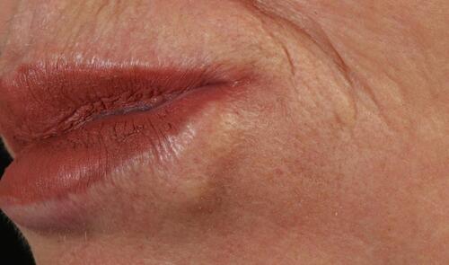
Figure 2 After 1 month: the test site with Volbella showed a positive reaction. Note: Image courtesy of Dr K De Boulle.
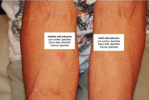
Figure 3 After 3 months: positive reaction for Juvederm Volbella and Volift. Note: Image courtesy of Dr K De Boulle.
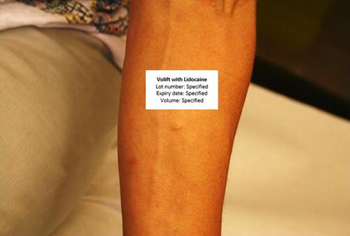
Figure 4 Artecoll granuloma (20 years) with exacerbation after Fractional resurfacing and subsequent HA layering. Note: Image courtesy of Dr K De Boulle.
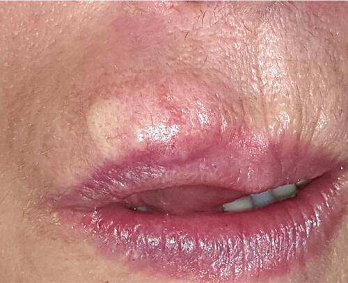
Table 3 Body Dysmorphic Disorder (BDD)
Figure 5 Valuable BDD screening questions. Note: Data adapted from Krebs et al.Citation34
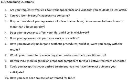
Table 4 Ethnicities: Features and Management
Table 5 Hyaluronidase Safety Aspects
Table 6 Hyaluronidase Practical Aspects
Table 7 Definitions
Table 8 HA Filler Degradation
Figure 6 Frankfort horizontal plane vs natural head position.
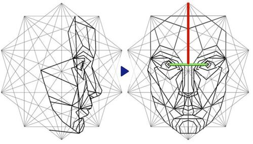
Figure 7 Illustration of the Frankfort horizontal plane, which often differs from natural head position, as viewed through a camera grid, superimposed on a skull and translated into pre-and post-photography.
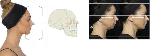
Figure 8 Shooting oblique view: (A) Align nasal tip to mid-pupil; (B) rotate head until all 4 canthi are visible. Note: Image courtesy of Woodrow Wilson.
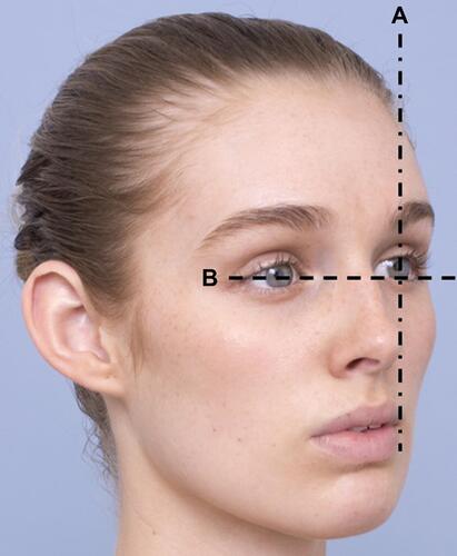
Figure 9 Selfie distortion: the effect of focal length, illustrating wide angle (28mm) distortion as seen with mobile photography. Note: Image courtesy of Dr Heydenrych.
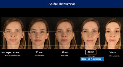
Figure 10 Topographical markings of foramina in anterior view. Note: Image courtesy of Dr Heydenrych.
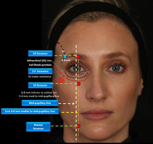
Figure 11 Oblique view illustrating topographical markings of bony landmarks and adjacent danger areas. Note: Image courtesy of Dr Heydenrych.

Figure 12 Temporal venous danger zone delineated by the upper margin of the zygomatic bone and a parallel horizontal line running from the K Point, at the junction of temporal crest (TC) and lateral orbital rim.
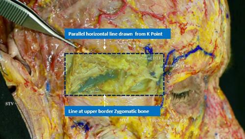
Table 9 Ten Topographical Tracings
Figure 13 Naked areas of facial artery. Notes: Reproduced with permission from Pirayesh A, Bertossi D, Heydenrych I, editors. Aesthetic Facial Anatomy Essentials for Injections. Boca Raton: CRC Press; 2020.Citation66 Copyright 2020 Taylor & Francis.
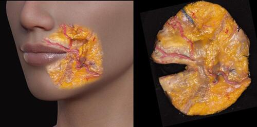
Figure 14 Diagram illustrating the most frequently affected choke anastomotic HA embolic sites.
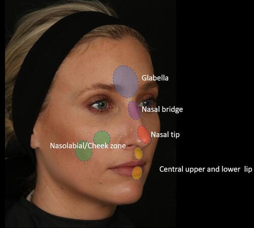
Table 10 Differences Between “Gentle Pinch” and “Deep Pinch” with Non-Dominant Hand During Temporal Injection
Figure 15 Vascular occlusion illustrating choke anastomotic distributions. Note: Images courtesy of Dr K De Boulle.
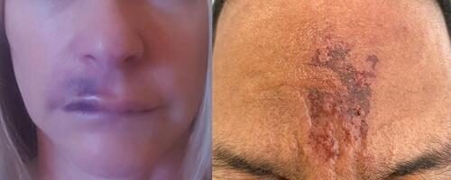
Figure 16 Vascular obstruction: 60 IU hyaluronidase under ultrasound guidance (A) pre-Rx (B) 2h post -Rx (C) 1-week post- Rx. Yellow circle denotes injection area. Note: Images courtesy of Dr Stefania Roberts.
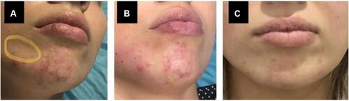
Figure 17 Ultrasound-guided Hyaluronidase treatment illustrating resolution of obstruction over 2 minutes (60 IU) Hyaluronidase. Note: Ultrasound images courtesy of Dr Stefania Roberts.
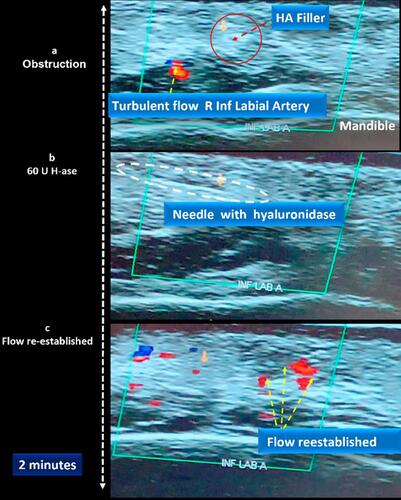
Figure 18 Needle Skills Worksheet. A laminated copy is used for regular extrusion practice utilizing sonar gel/expired products. Proprioceptive memory regarding volume control, needle resistance, and positional angulation may be refined. (A) Refining of volume control (B) refinement of needle course stability and angle.
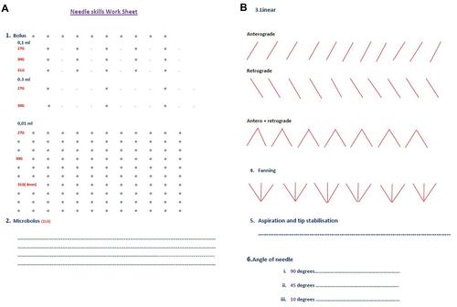
Figure 19 For upper forehead injections, the avascular subgaleal plane may be accessed with needle at 45 degrees to bone. Perpendicular injection may cause bevel height to extend to the vascular supragaleal plane.
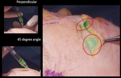
Figure 20 Early occurring symptoms.
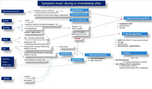
Table 11 Angles vs Depth (Needle or Cannula)
Figure 21 Late-occurring symptoms of LOAEs.
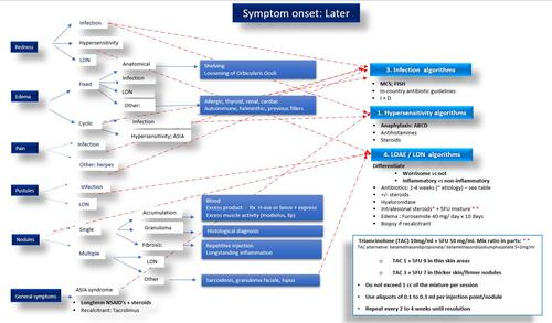
Figure 22 Classification of LOAEs.
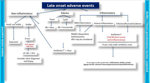
Figure 23 Patient demonstrating shelving Rx: surgery. Note: Image courtesy of Dr De Boulle.
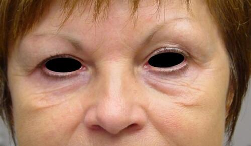
Figure 24 Differential diagnosis of swelling. 1 = edema; 2 = malar edema; 3 = late inflammatory response syndrome; 4 = late onset nodules (LON); 5 = persistent intermittent delayed swelling. Notes: Adapted with permission from Pirayesh A, Bertossi D, Heydenrych I, editors. Aesthetic Facial Anatomy Essentials for Injections. Boca Raton: CRC Press; 2020.Citation66 Copyright 2020 Taylor & Francis.
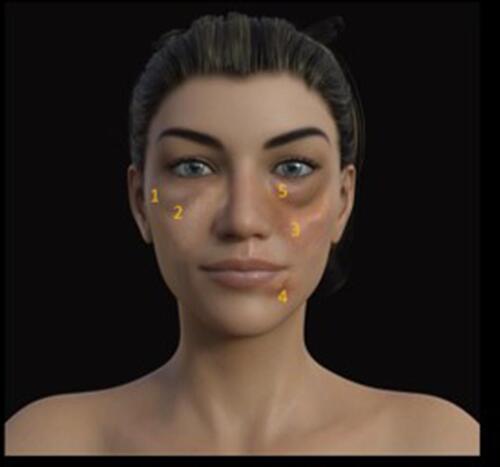
Figure 25 Temporal onset of post-procedural swelling. Notes: Reproduced with permission from Pirayesh A, Bertossi D, Heydenrych I, editors. Aesthetic Facial Anatomy Essentials for Injections. Boca Raton: CRC Press; 2020.66 Copyright 2020 Taylor & Francis.
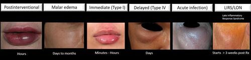
Figure 26 Patient demonstrating postprocedural swelling. Note: Image courtesy of Dr De Boulle.
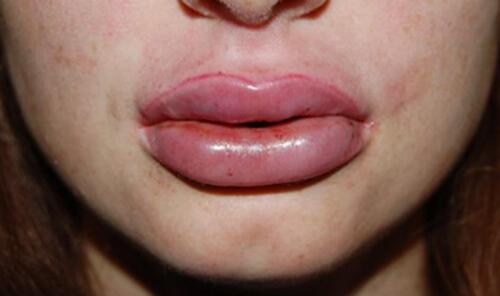
Figure 27 Patient demonstrating Type I hypersensitivity. Note: Image courtesy ofDr De Boulle.
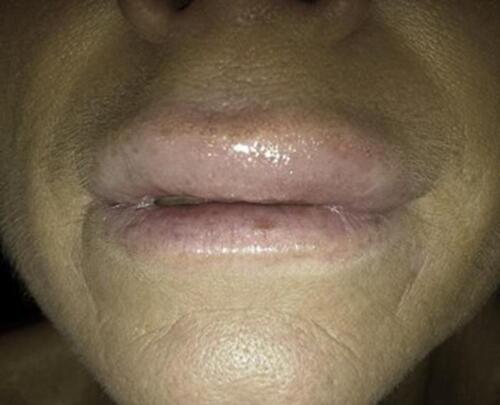
Figure 28 Evolution of a sterile abscess during the first-week post -filler. Rx: targeted antibiotic therapy, with incision and drainage, is vital to prevent tissue necrosis. This presentation may also occur as a late-onset event. Note: Image courtesy of Dr Heydenrych.
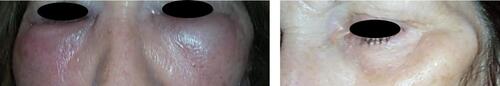
Figure 29 Differential diagnosis of skin discoloration: 1. Hematoma; 2. Ecchymosis; 3. Neovascularization; 4. Hyperpigmentation; 5. The Tyndall effect; 6. Ischaemia. Notes: Adapted with permission from Pirayesh A, Bertossi D, Heydenrych I, editors. Aesthetic Facial Anatomy Essentials for Injections. Boca Raton: CRC Press; 2020.Citation66 Copyright 2020 Taylor & Francis.
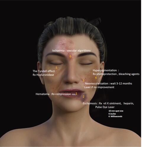
Figure 30 The clinical spectrum of LOAEs includes inflammatory or non-inflammatory manifestations, including swelling, induration, and nodules. Onset is usually after > 4 weeks.
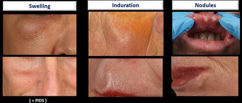
Table 12 Suggested Inclusions for Post-Procedure Checklist
Table 13 Management of Anaphylaxis with Emergency Crash Cart
Table 14 High-Dose Pulse Hyaluronidase (HDPH) for Intravascular Events.
Table 15 Prognosis
Table 16 A Suggested Practice Protocol for Managing Ophthalmic Incidents in the Aesthetic Practice
Figure 31 Patient with LOAE (nodule). Despite lack of improvement on long-term antibiotics, total resolution was affected with colchicine.
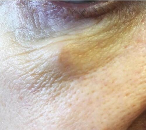
Figure 32 Patient with PIDS successfully treated with 0.1 mL of hyaluronidase. Note: Image courtesy of Dr A De Almeida.
Table 17 ASIA Syndrome: Summary
Table 18 Antibiotic Choice by Infection Origin (Adhere to Country-Specific Microbiotic Guidelines)