Figures & data

Figure 1 The all-purpose punch, showing the frustoconically shaped, textured cutting end and a flared cutting tip.
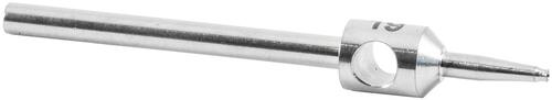
Figure 2 Patent application schematics demonstrating the advantage of a flared punch cutting tip. (A) Outer beveled punch tip shows cutting vectors directed towards the follicle; (B and C) the outer beveled punch transects the follicle before advancing to the follicle’s level (D) a flared punch with cutting vectors pointing away from the follicle (E and F) show minimal tendency to transect grafts while reaching deeper levels of the follicle, unlike the outer beveled punch.
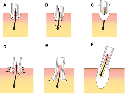
Figure 3 The diameter of an ordinarily flared punch (A) is broader than that of the all-purpose punch forged from the same outer-diameter punch and flared by coring the concavity of the first 1–2 mm of the tip (B).
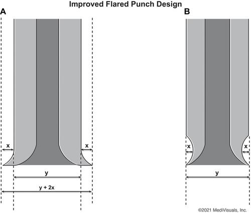
Figure 4 The wound-healing advantage of the flared all-purpose punch. (A) A1–A2: outer beveled punch cutting axis, directed downwards and inwards, cuts a cylindrical wound column with a relatively everted papillary dermal edge; A3: most of the wound closes primarily due to wound contraction. The top papillary portion remains patent, relying more on second intention healing for wound closure and resulting in a larger scar; (B) B1–B2: The flared punch cutting axis, directed outwards to bite into the tissue lateral to the punch. The first cut into the papillary dermis cuts a wound path that is relatively inverted compared to that of non-flared punches, resulting in a cylindrical wound column with a relatively inverted papillary dermal edge; B3: most of the wound closes primarily due to wound contraction, including the majority of the wound’s top papillary portion, bringing the edges closer together, such that the entire top part either closes by primary intention or recruits a relatively smaller degree of second intention, healing with less scarring.
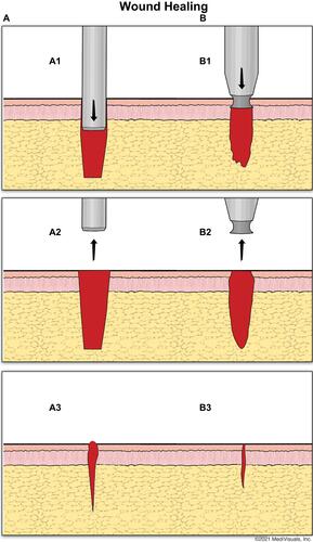
Figure 5 (A and B) Friction between the graft and punch lining – I causes the graft and punch to rotate in unison – II relative to the fixed distal portion of the graft, resulting in twisting and torsion damage – III (C) Frustoconical rooming of the punch lumen – IV minimizes friction between the inner surface of the punch and the graft – V thereby reducing the risk of torsion damage.
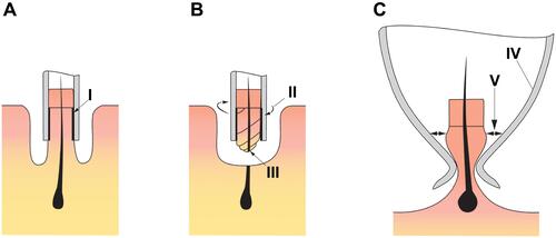
Figure 6 Patent application schematics show the texturing on the inside and outside of the punch.
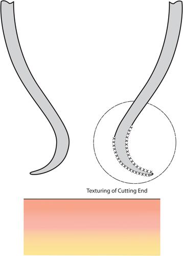
Figure 7 The angular point of the graft in the crosshairs of the cutting edge of advancing punches. (A) A conventional punch transects the angulated hair follicle at its maximum inflection point; (B) The textured all-purpose punch pulls the follicle, keeping the angulated portion inside the punch lumen before contacting the cutting tip of the punch.
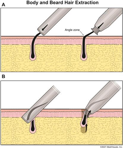
Figure 8 Patent application schematics demonstrating the crush injury phenomenon. (A) Friction impedes the follicle’s upward ascent, leading to the bulbar portion of the follicle – I to be crushed as the punch descends on it – II (B) Crush injury risk is minimized by the all-purpose punch’s texturing, which actively pulls the graft into the punch lumen. Impaction is further minimized by the punch’s spacious frustoconical design.
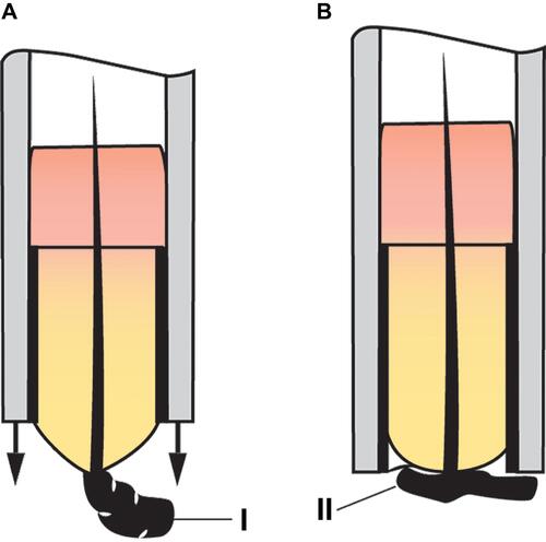
Figure 9 The frustoconical punch shape (A) increases the resistance with deeper punch penetration. (A) Resistance increases with the firmness and thickness of the tissue and (B) causes blunt separation of the lateral anchoring elements.
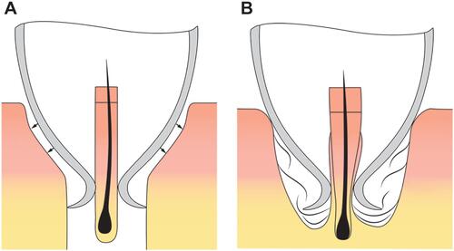
Figure 10 The all-purpose FUE device: (A) Main Panel: The system, consisting of the console, hand piece, foot pedal, and optional fluid integration. The dashboard shows six presets, custom mode, torque control, speed, timers, and reset features; (B) inset: The dashboard displays three movement modes, adjustable movement duration, score intervals, and automatic/manual modes.
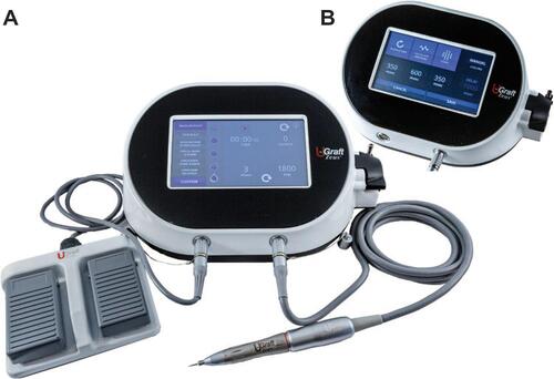
Figure 11 Case 1, a 63-year-old Caucasian male with Norwood (NW) 7 hair loss compounded by retrograde alopecia. (A) Bird’s eye view from the back; (B) right oblique view; and (C) bird’s eye view from the front.
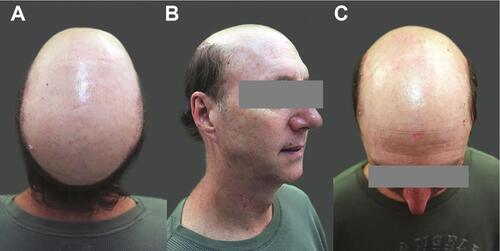
Figure 12 Case 1: Using the all-purpose FUE device, the Average Head Skin Thickness/Firmness, Body Hair Areas, and Beard Area hair presets were used for universal FUE. Post-operative photos of the head and beard: (A) forearm, (B) chest, and abdomen (C). Using hairs harvested from the head, beard, chest, stomach area, forearms, and pubic areas, global restoration was achieved. Results after one year: (D) Bird’s eye-view from the posterior; (E) right oblique view; and (F) bird’s eye-view from anterior.
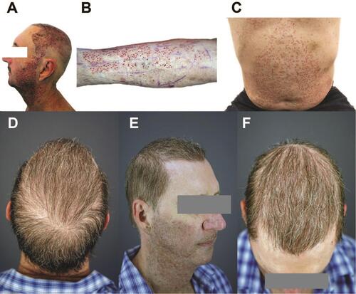
Figure 13 Case 2, a 26-year-old African American male undergoing FUE transplantation with the all-purpose FUE device set at moderate torque, oscillation mode, and an 18-G punch. (A) Frontal area before transplantation; (B) donor area showing chaotic hair exit angles; (C) the frontal area soon after grafting and the head donor area soon after extractions; and (D) results at 11 months after surgery.
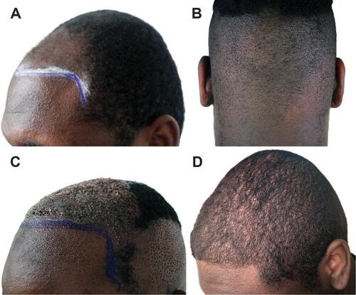
Figure 14 Case 3, a 33-year-old Caucasian male who requested non-shaven FUE with long hair to prevent obvious post-surgical scabbing and wanted to preview what the recipient area might look like with the final growth. The all-purpose FUE device extracted 3289 grafts in a 2.5-h period, with 90% long hair retrieval and a 3–4% graft attrition rate. (A) The frontal area before grafting; (B) long-hair grafts; and (C) hand piece alignment at 90 degrees obviates the need to guess the hair exit angle.
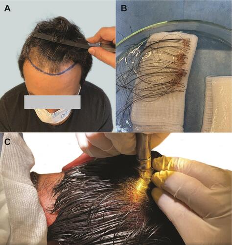
Figure 15 Case 3: (A) Frontal scalp soon after grafting; and (B) frontal area with minor signs of surgery at 48 h after long-hair implantation.
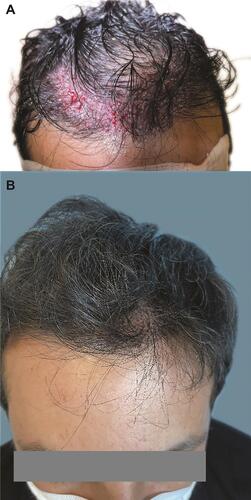
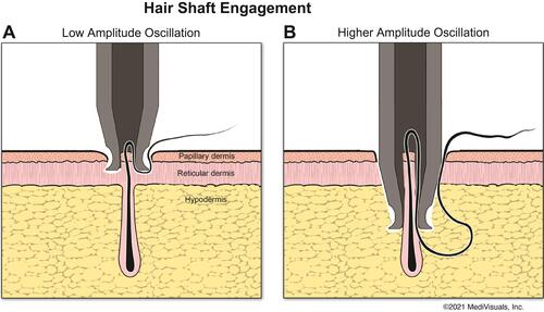
Figure 16 The benefits of short-arc oscillations in the dermal layer followed by larger arc oscillations in the hypodermis and of the internally roomed lumen, punch tip texturing, and hybrid punch design. (A) At the dermal level, with more rigid tissue, short arc oscillations minimize the chance of cutting the hair shaft. The relative bluntness of the all-purpose punch, which glides over the hair shaft rather than cutting it, facilitates the process. The frustoconical spaciousness provides room for tissue to gather and slide through, rather than getting impacted and subject to cutting; (B) deep to the dermis, the subcutaneous layer allows room for the hair shaft to maneuver away from the punch cutting tip; the movement mode switches to wider arc oscillations for a faster, more complete separation.