Figures & data
Figure 1 Dermoscopic features of patients with vitiligo. (a) Absent pigment network and sharp border (polarized light ×20); (b) faint pigment network (polarized light ×20); (c) perifollicular hyperpigmentation (yellow arrow, polarized light ×50); (d) perifollicular depigmentation (blue arrow, polarized light ×50); (e) micro-Koebner phenomenon (green arrow, polarized light ×20); (f) satellite phenomenon (black arrow, polarized light ×20).
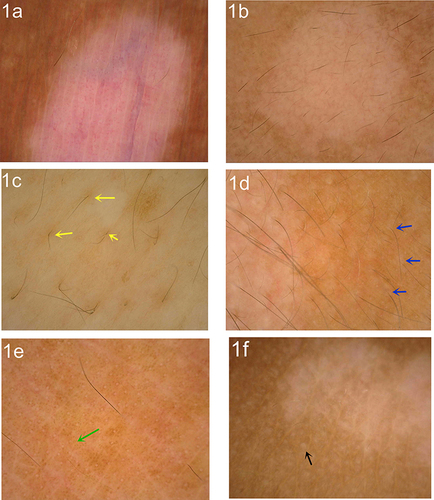
Figure 2 RCM features of patients with vitiligo. (a) Existence pigment rings in the basal layer of the lesion; (b) absence pigment rings in the basal layer of the lesion; (c) clear border (the red line shows the demarcation.); (d) ill-defined border; (e) inflammatory cell infiltration (yellow arrow); (f) dendritic melanocytes (blue arrow).
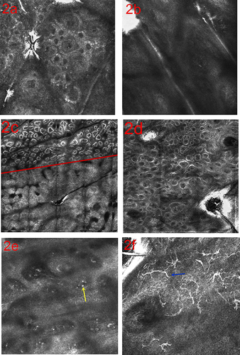
Table 1 Comparison of Vitiligo Activity by Different Skin Imaging Techniques [Cases (%)]
Table 2 Dermoscopic and RCM Features in Vitiligo Patients with Different Effect Response (Cases).
Table 3 Comparison of Baseline Characteristics of Dermoscopy and RCM in Vitiligo Patients with Different Treatment Effects (Cases).
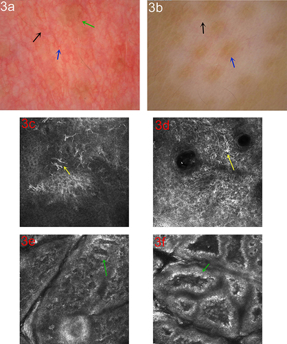
Figure 3 Dermoscopic and RCM changes in the process of treatment. (a) Dermoscopic observation showing increased pigment at the lesion (green arrow), white hair restoration (black arrow) and telangiectasia (blue arrow, polarized light ×50); (b) increased pigment around the hair follicle (blue arrow), white hair restoration (black arrow, polarized light ×20); (c) RCM observation of the repigmentation process showed dendritic melanocytes (yellow arrow); (d) starburst-like dendritic melanocytes (yellow arrow); (e) the pigment rings increased in the basal layer and were bent into a “mitochondrial crista-like” structure (green arrow); (f) Increase of pigment granules in the basal layer (green arrow).