Figures & data
Figure 1 Illustration of evenly distributed fat parcels in the recipient tissue bed.
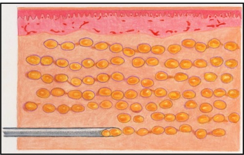
Figure 2 Illustration of fat distribution as a clump.
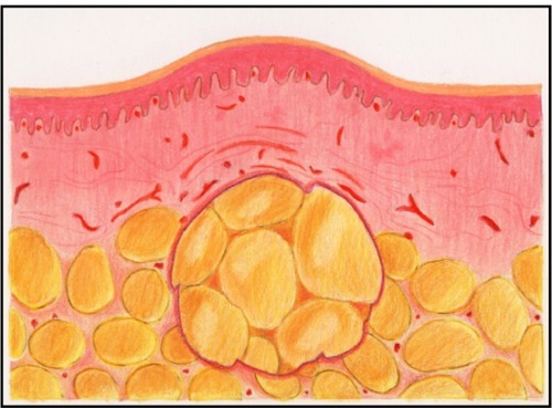
Figure 3 Illustration of tissue necrosis occurring when a large clump of fat is not amenable to neovascularization.
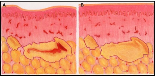
Figure 4 The injection control device (ICD).
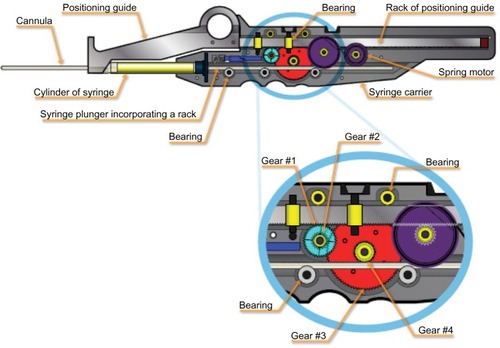
Figure 5 Injection control device (ICD) function.
Notes: (A) The device in the starting position. From this position, it is advanced as a unit, advancing the cannula into the tissue. (B) The cannula is inserted into the tissue. At this position, the positioning guide is secured stationary with respect to the patient’s skin surface. (C) The syringe carrier containing the syringe and cannula are withdrawn as a unit, causing the gear train to drive the plunger into the syringe and deposit the fat in a uniform thread. (D) The positioning guide has been released, and the spring motor has caused it to automatically retract into the syringe carrier, returning to the starting position. The cannula is slightly redirected and advanced into the tissue to repeat the cycle.
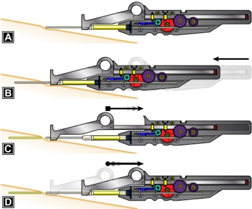
Figure 6 Drawing of face with zones and ports.
Notes: A, mid-facial region; B, upper lip extending superolaterally 5–10 mm beyond the melolabial fold; C, cheek; D, lower lip to the chin; E, vermillion of the upper lip; F, vermillion of the lower lip; G, hollow of the temple; H, superior eyelid; I, submandibular region; J, submental region; K, brow and supra-brow; L, glabella. 1, located approximately 1 cm lateral and inferior to the lateral canthus; 2, approximately 1 cm lateral to the oral commissure; 3, located at the jaw line approximately 1.5 cm lateral to a line drawn vertically through the oral commissure; 4, at the hairline, superior to the hollow of the temple; 5, junction of the alar lobule and the melolabial fold; 6, in the eyebrow, superior to the pupil; 7, in the eyebrow, superior to the medial canthus; 8, in the lateral portion of the malar mound, lateral to the end of the tear through crease; 9, lateral submentum of the jawline; 10, 2 cm superior to the brow in the mid-pupillary line; 11, 1 cm anterior to the tragus; 12, directly superior to the lateral canthus at the brow line.
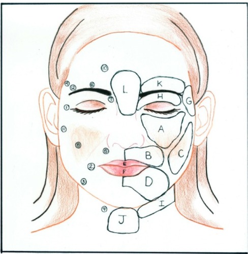
Figure 7 Drawing of face demonstrating crosshatch pattern.
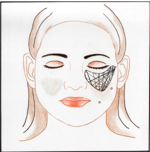
Table 1 List of patients, zones grafted, and associated procedures
Figure 8 Before (A) and 1-year postop (B).
Note: This 63-year-old patient had 112 cc fat grafted to the midface, cheeks, lips, upper eyelids, temples, brows, forehead, and neck.
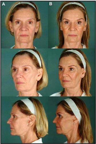
Figure 9 Before (A) and 4-month postop (B).
Note: This 43-year-old patient had 76 cc fat grafted to the midface, cheeks, lips, upper eyelids, temples, brows, and forehead.
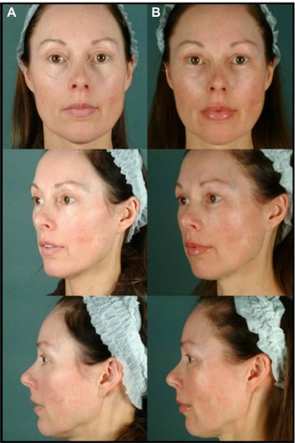
Figure 10 Before (A) and 6-month postop (B).
Note: This 48-year-old patient had 110 cc fat grafted to the midface, cheeks, lips, upper eyelids, temples, brows, and forehead.
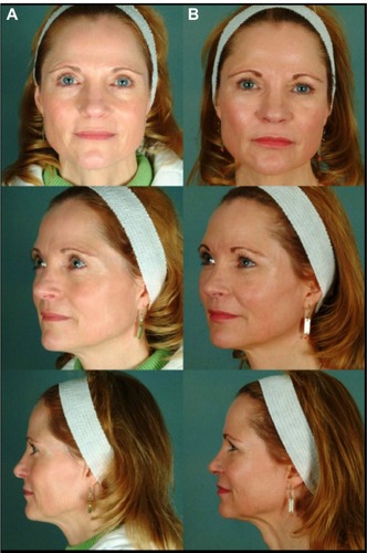
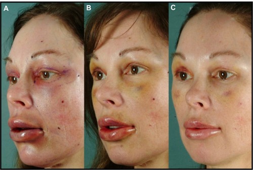
Figure 11 Sequential early postop photos at postoperative days 1 (A), 7 (B), and 14 (C).