
Figures & data
Figure 1 Teeth with TEC (A) and TREC (B) designs.
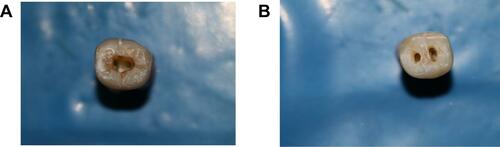
Figure 2 Determining the location and path of accessing the root canals through a TREC on the mesial and distal (A–C) and buccal and lingual (D and E) radiographs. The distance between the buccal and lingual surfaces of the teeth and also the distance between the mesial and distal surfaces of the teeth were determined (green and red dotted lines) and the perpendicular path to the occlusal surface was estimated to access the mesial and distal canal orifices such that the enamel-dentin bridge between the two access cavities was preserved. F shows the TREC access cavity and G shows the obturated canal along with a restored access cavity.
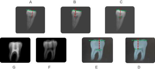
Figure 3 Photographs of the broken teeth in different groups of (A) control, (B) TEC, and (C) TREC.
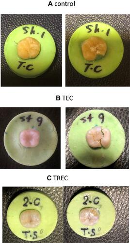
Table 1 Cross-Sectional Diameters, Buccolingual (BL), Mesiodistal (MD) Diameters (mm) and Comparison of Fracture Loads (N) of the Teeth (n=10)