Figures & data
Table 1 Physical Characteristics Related to Pyicnodysostosis Syndrome, Described in the Literature. The Table Demonstrates the Presence or Absence of Such Characteristics in the Reported Individual
Figure 1 Body aspect (A), frontal aspect (B) and lateral aspect (C) of the patient.
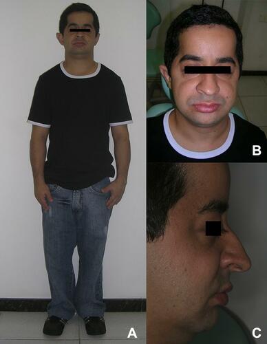
Figure 2 Radiological aspects of patient’s hand (A) and humerus and radius (B).
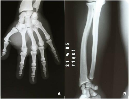
Figure 3 Initial panoramic radiograph.
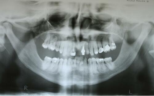
Figure 4 Initial lateral cephalogram.
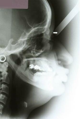
Figure 5 Initial intraoral photographs. (A) Right side view; (B) front view; (C) left side view.
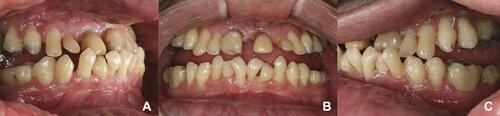
Figure 6 Full-mouth periapical X-ray.
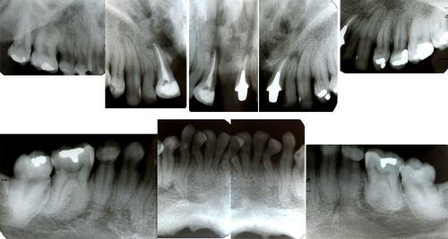
Figure 7 Initial impressions with a custom tray (A). Base plaque and wax guide plane performed over the patient teeth (B). Maxillomandibular records (C).
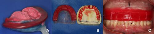
Figure 8 Reanatomization of lower incisors with composite resin. (A) Isolation with a rubber dam; (B) details of the isolation; (C) clinical aspects after the reanatomization.
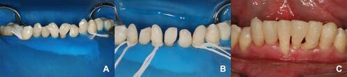
Figure 9 Final aspect of the first denture place over the teeth. (A) Right side view; (B) front view; (C) left side view.
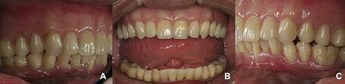
Figure 10 Panoramic radiograph after the O-rings installation (A). Occlusal view of the tree O-rings installed (B). Inner surface of the denture with the attachments placed on position (C).
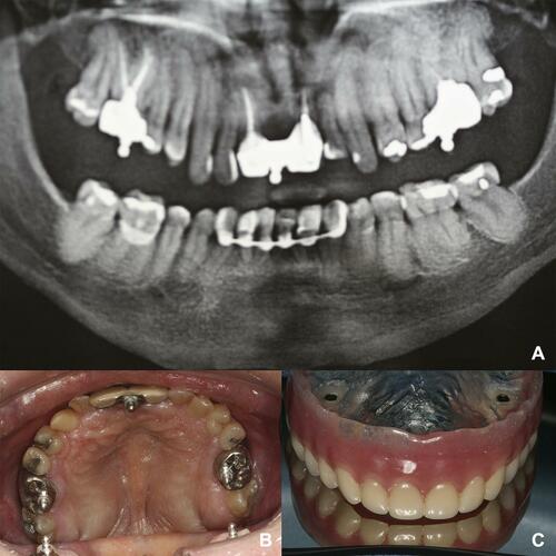
Figure 11 Frontal and lateral aspects of the patient before (A and B) and after (C and D) the rehabilitation procedure.
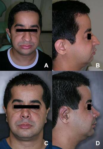
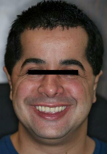
Figure 12 Final aspect of the patient with an improvement of esthetic appearance achieved with minimally invasive prosthetic approach.