Figures & data
Figure 1 Fluoroscopic views before endoscopic manipulation. (A and B) The drill was inserted to resect the LF and the ventral osteophytes on the SAP. (C and D) The working cannula was placed.
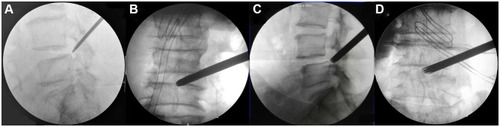
Figure 2 Intraoperative endoscopic views. (A and B) The superior endplate of the inferior vertebra (L5) was removed with an endoscopic bone knife. (C) Dorsal and ventral L5 nerve roots were fully decompressed. (D) The dura was torn with nucleus forceps. The white arrow represents the traversing nerve root (L5), and the black arrow represents the superior endplate of the inferior vertebra.
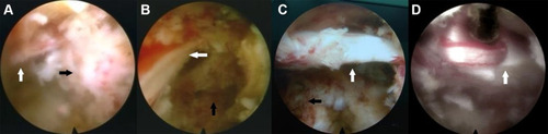
Table 1 Demographics of the Included Patients
Table 2 Comorbidities
Figure 3 Clinical outcomes before and after PTED at different follow-up time points. (A) The VAS-leg pain scores. (B) ODI before and after PTED. (C) Outcome of the modified MacNab criteria.
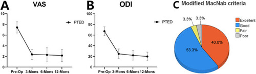
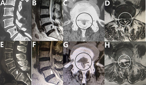
Figure 4 Pre- and postoperative CT and MRI. (A and B) The superior endplate of the inferior vertebra (arrow) before surgery. (C and D) Central spinal canal stenosis (circle). (E and F) The protruding vertebral bone was removed (arrow), and this procedure led to restoration of the original spinal canal shape. (G and H) The central spinal canal (circle) was enlarged. The superior endplate of the inferior vertebra was indicated by arrow. The central spinal canal stenosis and the enlarged central spinal canal was indicated by circle.