Figures & data
Figure 1 Posterior spine indicating the four nerve roots traversing and exiting on the ipsilateral and contralateral side, decompressed through a single interlaminar access point.
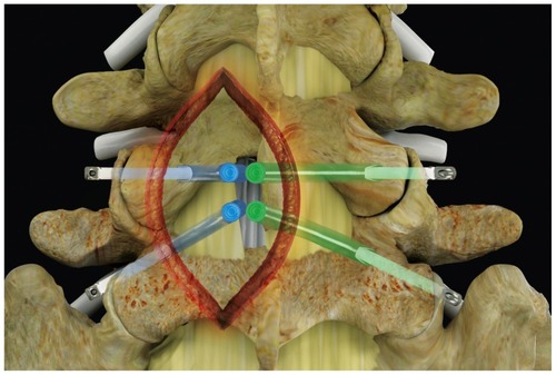
Figure 2 The iO-Flex® system consists of (from top to bottom) a distal handle, a MicroBlade Shaver® instrument (available in 5.5 mm, 7.5 mm [shown], 10 mm, and 12 mm widths), the Neuro Check® device, and a probe (ipsilateral [shown], contralateral [not shown]).
![Figure 2 The iO-Flex® system consists of (from top to bottom) a distal handle, a MicroBlade Shaver® instrument (available in 5.5 mm, 7.5 mm [shown], 10 mm, and 12 mm widths), the Neuro Check® device, and a probe (ipsilateral [shown], contralateral [not shown]).](/cms/asset/d62ec592-aa87-497a-945c-0db4bf71ad5d/dcia_a_32536_f0002_c.jpg)
Figure 3 After the probe has been properly inserted and the wire has been delivered, the iO-Flex® MicroBlade Shaver® is passed through the epidural space and out of the lateral foramen.
Note: Tissue is removed using a bimanual reciprocating motion.
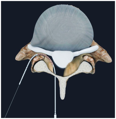
Figure 4 Preoperative and postoperative assessment of decompression using fluoroscopy and a Woodson probe (lateral images [left to right]: pretreatment with MicroBlade Shaver® instrument, post-treatment with MicroBlade Shaver instrument, and post-treatment assessment with Woodson probe).
![Figure 4 Preoperative and postoperative assessment of decompression using fluoroscopy and a Woodson probe (lateral images [left to right]: pretreatment with MicroBlade Shaver® instrument, post-treatment with MicroBlade Shaver instrument, and post-treatment assessment with Woodson probe).](/cms/asset/b1d2743c-dd35-45ef-b7e5-f6defd360d9d/dcia_a_32536_f0004_b.jpg)
Figure 5 Example of measurements made from reconstructed parasagittal computed tomography slices bisecting the cranial and caudal pedicles at the level of interest. (A) Foraminal width, measured at the narrowest part of the foramen and (B) foraminal area.
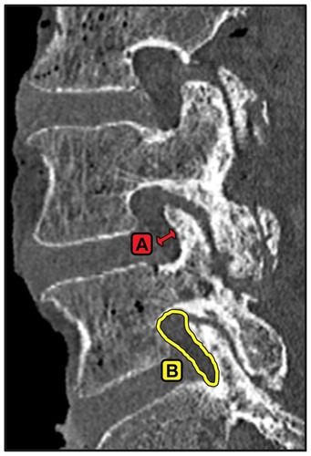
Figure 6 Example of measurements made from reconstructed axial slices through the center of the intervertebral disc space aligned with the inferior endplate at the level of interest. (A) Bony canal area, (B) soft tissue canal area, (C) ligamentum flavum area, (D) lateral recess diameter, (E) facet area, and (F) facet width.
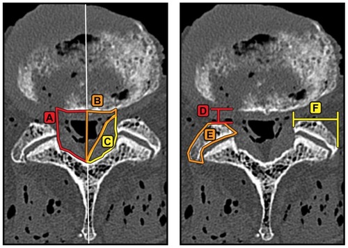
Table 1 Anatomical lumbar changes following use of the iO-Flex® system and of hemilaminotomy with foraminotomy in nondiseased cadaveric lumbar specimens
Table 2 Anatomical lumbar changes following use of the iO-Flex® system and of hemilaminotomy with foraminotomy in stenotic cadaveric specimens
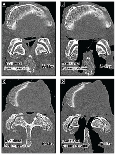
Figure 7 Reconstructed axial computed tomography scans illustrating the ability of the iO-Flex® system to decompress the lateral recess and foramen effectively while maintaining facet joint integrity. Images are provided for nondiseased preoperative (A) and postoperative (B) specimens as well as stenotic preoperative (C) and postoperative (D) specimens.