Figures & data
Figure 1 (A) Percutaneous Curved Vertebroplasty Device; (B) The bone cement distribution of PCVP is kidney-shaped and mainly located in the anterior and middle of the vertebral body; (C) insert curved injection cannula via straight trocar into the contralateral hemivertebra body; (D and E) The bone cement was injected with the cannula withdrawn point-by-point.
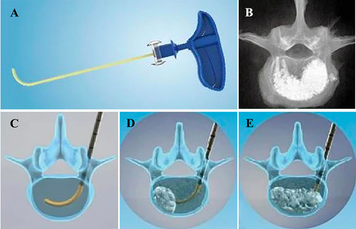
Figure 2 (A–H) Intraoperative fluoroscopy imaging obtained during percutaneous curved vertebroplasty. After the introducer accessed into optimal position, the curved injection cannula is inserted. The tip crossed the midline on anteroposterior fluoroscopy and at the forepart of the vertebra body on lateral fluoroscopy. The bone cement was distributed in both sides of the vertebra.
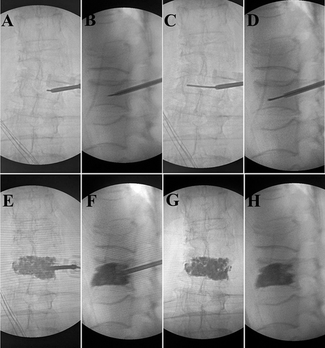
Table 1 Pre-Operative Demographic Data of Patients of Two Groups
Table 2 Pre- and Post-Operative VAS and ODI of Two Groups
Table 3 Surgical Parameters of Two Groups
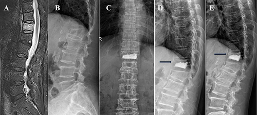
Figure 3 A 70 years old male patient with T12 vertebral compression fracture underwent PKP. (A) T2 fat suppression MRI showed a fresh compression fracture of T12; (B) preoperative lateral fluoroscopy; (C and D) anteroposterior and lateral fluoroscopy 1 day post operation; (E) Lateral plain film at 1 month post operation showed the treated vertebra recollapsed and diffusely injected PMMA was condensed.
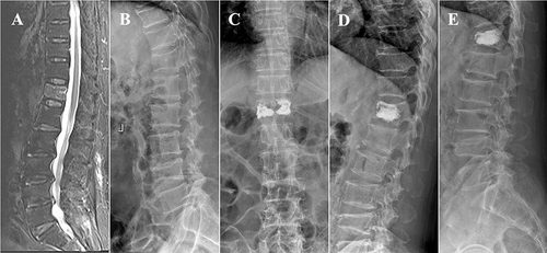
Figure 4 A 65 years old female patient with T12 vertebra compression fracture underwent PCVP. (A) T2 fat suppression MRI showed a fresh compression fracture of T12; (B) preoperative lateral fluoroscopy; (C and D) anteroposterior and lateral fluoroscopy 1 day post operation showed that the cement did not contact the upper endplate (black arrow); (E) The X-ray at 1 month post operation showed the uncemented portions of treated vertebra recollapsed and refracture occurred (black arrow).