Figures & data
Figure 1 Photographs and schematic diagrams of the customized balance rehabilitation training equipment.
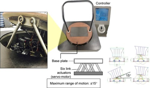
Figure 2 The dynamic rotation of participants induced by rotation of the base plate: (A) AP, (B) RD, (C) ML, and (D) LD.
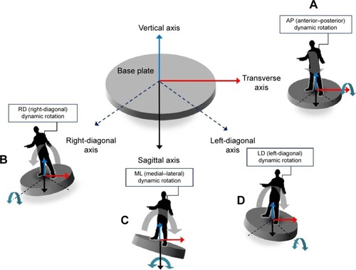
Figure 3 The experimental configuration used to generate and characterize the motion of the participants.
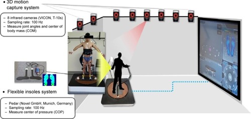
Figure 4 Variations in the joint angles of the lower extremities in response to rotation of the base plate of the balance rehabilitation training equipment.
Notes: The hip joint (A), the knee joint (B), and the ankle joint (C). *Statistical significance (P<0.05).
Abbreviations: AP, anterior–posterior; RD, right-diagonal; ML, medial–lateral; LD, left-diagonal.
Abbreviations: AP, anterior–posterior; RD, right-diagonal; ML, medial–lateral; LD, left-diagonal.
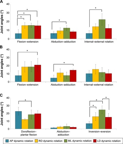
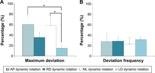
Figure 5 Results of balance characteristics in response to rotation of the base plate.
Notes: The maximum deviation (A) and the deviation frequency (B). *Statistical significance (P<0.05).
Abbreviations: AP, anterior–posterior; RD, right-diagonal; ML, medial–lateral; LD, left-diagonal.
Abbreviations: AP, anterior–posterior; RD, right-diagonal; ML, medial–lateral; LD, left-diagonal.