Figures & data
Figure 1 Space coordinates transformation relationships in US probe calibration.
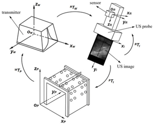
Figure 2 (A) 3D printed slider. (B) The slider controlled the direction of the US probe.
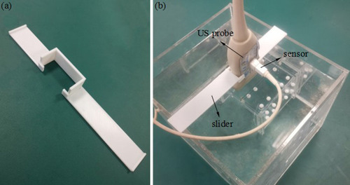
Figure 3 (A) The micro electromagnetic sensor was fixed to the needle. (B) The electromagnetic sensor was fixed to the needle. (C) The microsensor was located at the end of the needle shaft.
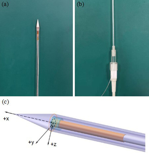
Figure 4 The phantom.
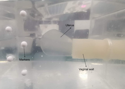
Figure 5 The workflow of the phantom experiment.
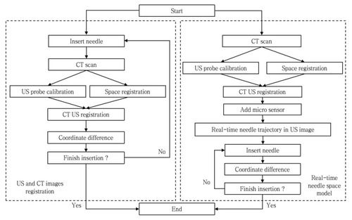
Figure 6 Histogram of the marker sphere centers’ coordinate differences between CT images and registered US images for 30 markers.
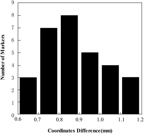
Figure 7 Histogram of coordinate differences between US images and registered CT images in the axial plane (black columns) for 30 markers and the sagittal plane (grey columns) for 12 markers.
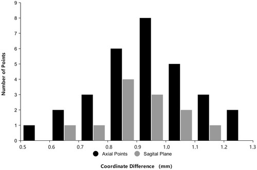
Figure 8 Histogram of coordinate differences between the registration US images and needle’s real-time space model for 30 markers.
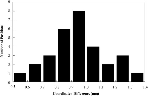
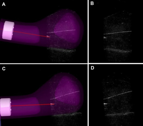
Figure 9 The registration between the US image and the needle’s real-time space model in the insertion path. (A, C) Show the registration between US images and interstitial needle’s real-time space model at two of the five positions in two insertion paths. (B, D) Show the US images at two of the five positions in two insertion paths.