
Figures & data
Figure 1 Example of target delineation of the target volume (M-PTV) for NSCLC radiotherapy. (A), the yellow area represents the mediastinal area (M) outlined in the general drawing. (B). The purple area represents the PTV area (PTV). (C), The blue area represents the target area of the study, which is the mediastinal area minus P (M-PTV). (D) represents the general layout.
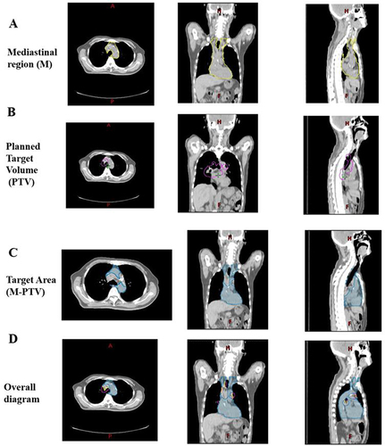
Table 1 Baseline Characteristics of Patients
Figure 2 Changes in circulating immune cell subsets before and after radiotherapy. (A)–(I) represent the changes in lymphocyte and immune cell subsets before and after radiotherapy. After radiotherapy, CD3+T cells, CD8+T cells, and CD8/Treg increased, while CD4+T cells, CD4/CD8, and B cells decreased significantly (P<0.05). There was no statistically significant difference in lymphocytes, NK cells, and Treg cells (P>0.05). Pre RT, before radiotherapy; Post RT: After radiotherapy. (A) The Y-axis of the graph has no units. (B) The Y-axis of the graph has units of “% Lymphs”, (C) The Y-axis of the graph has units of “% Lymphs”, (D) The Y-axis of the graph has units of “% Lymphs”, (E) The Y-axis of the graph has no units, (F) The Y-axis of the graph has units of “% Lymphs”, (G) The Y-axis of the graph has units of “% Lymphs”, (H) The Y-axis of the graph has units of “% CD4+T Lymphs”, (I) The Y-axis of the graph has no units.
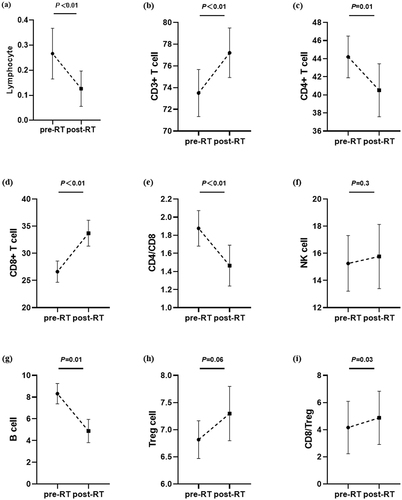
Figure 3 Receiver operating characteristic (ROC) curves for short-term response and circulating immune cell subsets in all patients. Area under lymphocyte ratio curve AUC=0.63 (light blue line), area under CD3+T cell ratio curve AUC=0.51 (red line), area under CD4+T cell ratio curve AUC=0.73 (dark green line), area under CD8+T cell ratio curve AUC=0.75 (Orange line), area under CD4/CD8 ratio curve AUC=0.74 (yellow line), area under NK cell ratio curve AUC=0.54 (blue green line), The area under the B cell ratio curve AUC=0.46 (pink line), the area under the Treg cell ratio curve AUC=0.50 (purple line), and the area under the CD8/Treg ratio curve AUC=0.68 (green line). LymR, post radiotherapy: lymphocyte ratio before radiotherapy; CD3R, post radiotherapy: CD3+T cell ratio before radiotherapy; CD4R, post radiotherapy: CD4+T cell ratio before radiotherapy; CD8R, post radiotherapy: CD8+T cell ratio before radiotherapy; CD4/CD8R, after radiotherapy: CD4/CD8 ratio before radiotherapy; NKR, post radiotherapy: NK cell ratio before radiotherapy; BR, after radiotherapy: B cell ratio before radiotherapy; TregR, post radiotherapy: Treg cell ratio before radiotherapy; CD8/TregR, post radiotherapy: CD8/Treg ratio before radiotherapy.
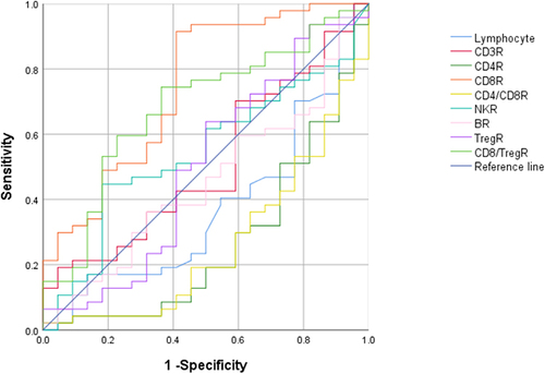
Table 2 Circulating Immune Subgroup ORR
Table 3 Univariate and Logistic Regression Analysis of Factors Affecting Short-Term Efficacy of Radiotherapy
Figure 4 Receiver operating characteristic curves (ROC) for dose parameters. AUC under V2 curve=0.68 (blue line), AUC under V5 curve=0.62 (red line), and AUC under V10 curve=0.56 (green line); Area under V20 curve AUC=0.56 (Orange line); Area under V30 curve AUC=0.60 (yellow line); Area under V40 curve AUC=0.58 (blue green line); Area under V50 curve AUC=0.58 (pink line); V2, the volume subjected to 200cGy irradiation; V5, the volume subjected to 500cGy irradiation; V10; Volume of exposure to 1000cGy; V20,; The volume of exposure to 2000cGy; V30, volume irradiated with 3000cGy; V40, volume irradiated with 4000cGy; V50, the volume subjected to 5000cGy irradiation.
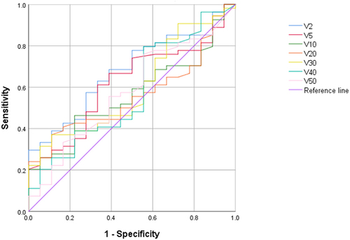
Table 4 Binary Logistic Regression Analysis of Radiotherapy Parameters and CD8+ T Cells
Data Sharing Statement
The datasets used and analyzed during the current study are available from the corresponding author on reasonable request.