Figures & data
Figure 1 Area under the forced expiratory FVL is determined by integrating all flow-volume measurement points of the observed FVL.
Abbreviations: AreaFE%, area under the forced expiratory flow-volume loop expressed as a percentage of the reference value; FEFx, forced expiratory flow at x (25%, 50% or 75%) of FVC; FVL, flow-volume loop; PEF, peak expiratory flow; pred, predicted values.
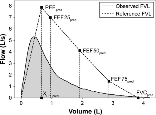
Figure 2 Presence of severe static hyperinflation (shown in black) in cohort A (n=215) according to (A) RV/TLC >60% and (B) IC/TLC <25% across all GOLD stages.
Note: No patient in GOLD I and more than 80% patients in GOLD IV had severe hyperinflation according to both criteria.
Abbreviations: IC, inspiratory capacity measured using body plethysmography; RV, residual volume; TLC, total lung capacity.
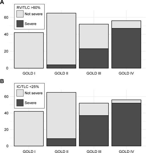
Figure 3 Distribution of AreaFE% in each GOLD stage is shown: it decreases significantly with airflow obstruction severity from GOLD I to GOLD IV (P<0.0001).
Abbreviation: AreaFE%, area under the forced expiratory flow-volume loop expressed as a percentage of the reference value.
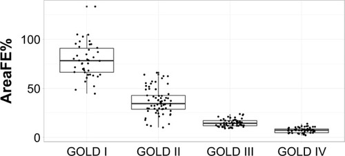
Table 1 Baseline characteristics of cohort A (n=215)
Table 2 Correlations of AreaFE% and conventional spirometry parameters with RV/TLC and IC/TLC in sub-cohort A (GOLD II, III and IV subjects from cohort A, n=173)
Figure 4 Distribution of the area under the forced expiratory flow-volume loop expressed as a percentage of the reference value (AreaFE%) in sub-cohort A (GOLD II, III and IV subjects from cohort A, n=173) shown against (A) RV/TLC and (B) IC/TLC.
Abbreviations: AreaFE%, area under the forced expiratory flow-volume loop expressed as a percentage of the reference value; IC, inspiratory capacity measured using body plethysmography; ROC, receiver operating characteristics; RV, residual volume; TLC, total lung capacity.
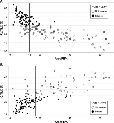
Table 3 ROC cut-offs developed in sub-cohort A (GOLD II, III and IV subjects from cohort A, n=173) and validation in sub-cohort B (GOLD II, III and IV subjects from cohort B, n=75)
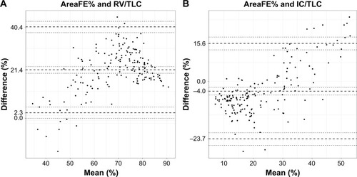
Figure 5 Bland–Altman plots showing (A) the difference of 100-AreaFE% and RV/TLC against their mean and (B) the difference of AreaFE% and IC/TLC against their mean.
Abbreviations: AreaFE%, area under the forced expiratory flow-volume loop expressed as a percentage of the reference; IC, inspiratory capacity measured using body plethysmography; RV, residual volume; TLC, total lung capacity.