Figures & data
Figure 1 Schematic representation of the concept behind ultrasound-triggered drug delivery.
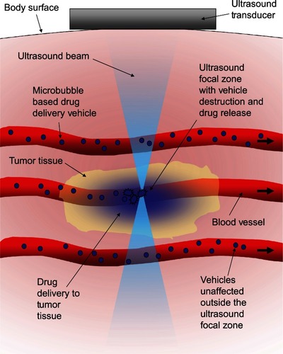
Figure 2 In-vitro demonstration of the localized activation of microbubble-based drug delivery vehicles. An agar tissue phantom with a molded channel down the center was used to model a blood vessel. Avidin was coated on the surface of the entire channel to simulate a targeting molecule. Fluorescently labeled drug-delivery vehicles containing a microbubble were introduced into the entire length of the channel. The inside of the vehicles were biotinylated to cause binding to the avidin-coated channels when exposed by ultrasound-induced vehicle rupture. (A) The focal zone of the ultrasound beam. (B) The fluorescent vehicles were introduced to the channel then washed out with water with no ultrasound exposure to demonstrate the background level of nonspecific binding. (C) When low intensity ultrasound was applied, only the vehicles in the focal zone were fragmented revealing the biotin which allowed binding to occur to the avidin-coated channel walls. This marked the location of activation. Vehicles were distributed throughout the channel, but only those that were activated were left behind after washing. (D) Higher intensity ultrasound caused a larger number of vehicle activations and expanded the effective focal zone over which activation would occur.
Reprinted from Ibsen S, Benchimol M, Simberg D, Schutt C, Steiner J, Esener S. A novel nested liposome drug delivery vehicle capable of ultrasound triggered release of its payload. J Control Release. 2011;155(3):358–366, Copyright 2011, with permission from Elsevier.Citation38
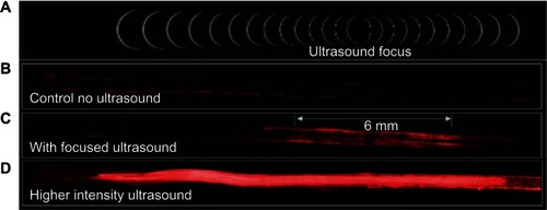
Figure 3 Images of microbubbles taken just after manufacturing. (A) White light illumination of the microbubbles. The density difference between the gas inside the microbubble and the surrounding water caused them to behave like lenses making them appear as dark circles with ring structures around them. (B) Fluorescent image of the same field of microbubbles showing the fluorescent dye that had been incorporated into the stabilizing lipid monolayer surrounding each microbubble.
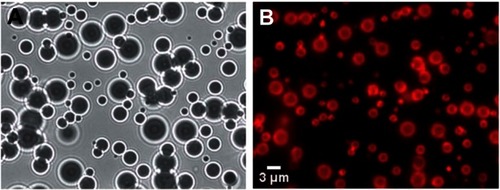
Figure 4 Streak camera images of a microbubble undergoing size oscillations when exposed to ultrasound. (A) The original resting size of the microbubble. (B) As the ultrasound pulse hit the microbubble the rarefaction portion caused the microbubble to expand. (C) The microbubble was destroyed, and remnant gas fragments were left behind. (D) All the remnant gas dissolved into the water. (E) A streak camera image showing only the width of the microbubble as a function of time, documenting how the diameter changed over the course of the ultrasound exposure.
Reprinted with permission from Bloch SH, Wan M, Dayton PA, Ferrara KW. Optical observation of lipid-and polymer-shelled ultrasound microbubble contrast agents. Appl Phys Lett. 2004;84(4):631–633. Copyright 2004, American Institute of Physics.Citation58
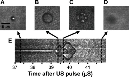
Figure 5 Microbubble interactions with ultrasound. (A) The microbubble diameter changes when exposed to the pressure waves of ultrasound. During the compression portion of the wave the microbubble diameter shrinks, while during rarefaction the microbubble expands. The diameter can change by a factor of eight between these two states. (B) Pressure differences are created around the microbubble as it undergoes vibrational size changes, driving the surrounding fluid to flow around it in various patterns. This microstreaming can be used to disrupt nearby membranes. (C) When resonance is achieved between the microbubble oscillations and the driving ultrasound frequency, the microbubble can undergo an adiabatic implosion.
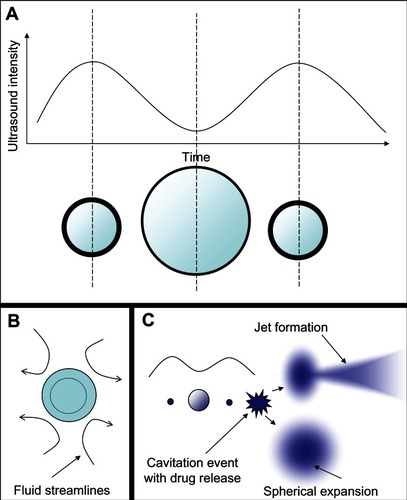
Figure 6 Different microstreaming fluid flow patterns around microbubbles oscillating in diameter under the influence of ultrasound. The microbubbles are the dark circles with white outlines in the center of each frame. The little white dots are particles that mark the streamlines of fluid flow patterns in the surrounding water. The microbubbles are all roughly the same size in each frame, and the different flow patterns shown in frames (A–C) arise from different driving ultrasound frequencies. Reprinted from Collis J, Manasseh R, Liovic P, et al. Cavitation microstreaming and stress fields created by microbubbles. Ultrasonics. 2010;50(2):273–279. Copyright 2010, with permission from Elsevier.Citation70
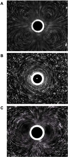
Figure 7 Still images from a high speed video of a microbubble undergoing asymmetric collapse during inertial cavitation creating a fluid jet. (A) The original microbubble before ultrasound exposure. (B) A schematic of the microbubble outline before ultrasound exposure. (C) The microbubble during ultrasound exposure, undergoing an asymmetric collapse where the left side actually collapsed through the airspace of the microbubble and penetrated through the right side. (D) Schematic showing the microbubble outline during collapse. (E) Overlaid images of the microbubble before ultrasound exposure and during collapse. (F) Schematic of the before and during ultrasound exposure outlines of the microbubble.
Reproduced from Postema et al.Citation61
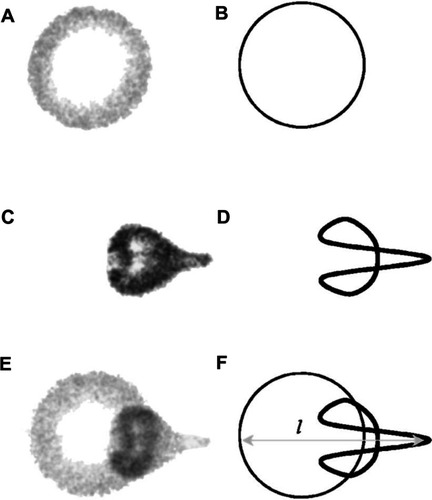
Figure 8 Schematic representation of ultrasound-triggered drug delivery on the cellular level.
Notes: Microbubble-based drug-delivery vehicles flow through the vasculature into the ultrasound focal zone within the tumor region where they undergo cavitation. Microbubbles on the edge of the focal zone undergo some vibration, resulting in microstreaming. These two mechanisms help to increase the permeability of the cell membranes of the nearby endothelial cells, facilitating drug delivery to the tumor neovasculature. The inherent leakiness of the tumor vasculature allows some of the released drug to gain access to the tumor cells, which can be enhanced though damage done to the vasculature by the inertial cavitation shockwave. The concentration of the drug in the tumor circulation increases with further ultrasound pulses that allow fresh vehicles to enter the tumor. Over time, the drug has a chance to spread further into the tumor tissue. Drug that is not taken up by the tumor is swept downstream where it is diluted into systemic circulation, creating a dramatically smaller systemic dose than would be encountered by simply injecting the free drug into circulation.
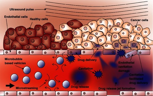
Figure 9 Schematic representations of various drug-delivery vehicle designs. (A) The basic microbubble design with a lipid monolayer stabilizing the PFC/air gas core. Targeting ligands can be conjugated to the surface to help facilitate accumulation of the microbubble in desired tissues. These ligands can be antibodies or short peptide sequences such as cyclic RGD. (B) The microbubble itself can be a vehicle by attaching drugs and even DNA to the surface through the use of electrostatic attractions. (C) Lipophilic drugs can be incorporated into the lipid monolayer shell of the microbubble. (D) The stabilizing shell can be thickened with an oil layer, allowing hydrophobic drugs to be carried within it. (E) Drug-filled liposomes can be attached to the surface of the microbubble. When the microbubble is exposed to ultrasound, the liposomes are disrupted by the mechanical actuation releasing drug. (F) The microbubble can be encapsulated within a liposome along with the drug. When exposed to ultrasound, the microbubble ruptures the outer liposome, releasing the payload.
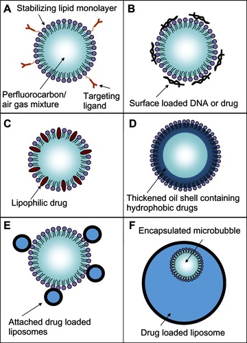
Figure 10 Rupture and payload release patterns of drug-delivery vehicles containing a microbubble. (A) The SHERPA drug-delivery particle contained a microbubble within a fluorescently labeled liposome and is indicated by the red circle. Upon ultrasound exposure, the microbubble underwent inertial cavitation and shattered the surrounding lipid membrane, creating a debris field of lipid particles and a jet. (B) At lower intensity, the ultrasound pulse caused the microbubble to undergo microstreaming instead of inertial cavitation, causing a single rupture in the surrounding lipid membrane with subsequent slow opening as a single piece.
Reprinted from Ibsen S, Benchimol M, Simberg D, Schutt C, Steiner J, Esener S. A novel nested liposome drug delivery vehicle capable of ultrasound triggered release of its payload. J Control Release. 2011;155(3):358–366, Copyright 2011, with permission from Elsevier.Citation38
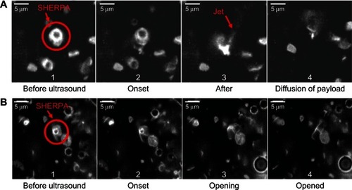
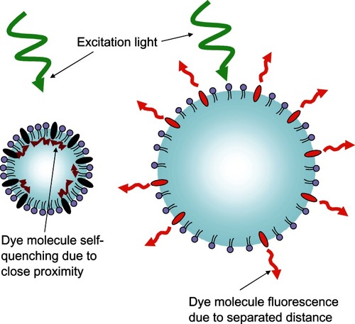
Figure 11 Schematic representation of the fluorescent light-modulating “blinking” microbubble contrast agent.