
Figures & data
Figure 1 Currently active vision prosthesis research groups, as of January 2016.
Notes: Courtesy of Professor Joe Rizzo, Dr Lauren Ayton, and the Detroit Institute of Ophthalmology.
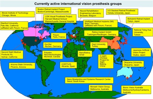
Figure 2 Locations of vision prostheses.
Notes: A schematic of the visual pathway as drawn from the ventral side of the brain with the inset box depicting the retinal sites of visual prosthesis implants. Visual prosthesis devices have been implanted at the following locations: within the eye and retina (R) at a, epiretinal; b, subretinal; c, suprachoroidal; and d, intrascleral sites, the optic nerve, the LGN and within the visual cortex, adjacent to the CF. Electrical stimulation at these sites elicits phosphenes that can be used to create low-resolution vision.
Abbreviations: CF, calcarine fissure; LGN, lateral geniculate nucleus; R, retina.
Abbreviations: CF, calcarine fissure; LGN, lateral geniculate nucleus; R, retina.
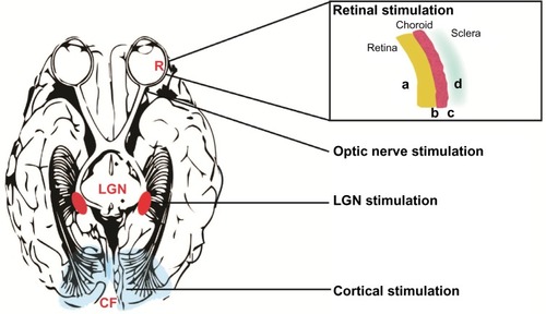
Figure 3 Examples of the simulated phosphenes (single and patterned) and their characteristics as reported by patients.
Notes: The theoretically expected phosphene from electrical stimulation of the visual pathway is a white (colorless) circle (A). Other shapes have been reported, such as dots, donut-shaped circles, lines, squares, triangles, and matchsticks (B). Patterns of phosphenes elicited can form an image (the letter E), as depicted on a 5×5 electrode array (C). The stimulus, a red E, is shown in the lower corner.
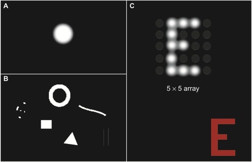
Figure 4 Schematic of a classical prosthesis with a retinal implant (A) and optical sensor prosthesis (B).
Notes: Classical prosthesis requires a camera (1) to capture images. The image (a cat) is then processed externally (2) and converted to an electrical stimulation pattern that is transmitted by a wireless receiver (3) to the retinal implant (4) to elicit phosphenes. Optical sensor prosthesis relies on image capture by a subretinally implanted array (1). The light signal is amplified by power derived from an external battery source (2) that is connected using a cable (3). The multiphotodiode array is able to elicit phosphenes within the retina without the use of a camera and visual processing package.
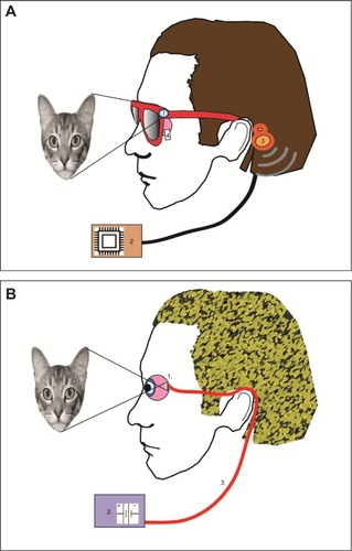
Table 1 Summary of the vision prosthesis clinical trials completed to date