
Figures & data
Figure 1 Coronal-oblique MIP CT images and VR CT images of portosystemic shunts.
Notes: (A) Lienorenal shunt draining into the inferior aspect of left renal vein (arrow). (B) Lienorenal shunt arising from the splenoportal confluence (arrowhead) and draining into the superior aspect of the left renal vein (arrows). (C) A lienorenal shunt similar to the one shown in B, which, however, is arising from the splenic vein (arrowheads in B and C). (D) A tortuous gastrosplenorenal shunt (arrowheads). (E) Tortuous mesocaval shunts (SMV; arrow points to the efferent vein draining into the inferior vena cava). (F) The VR image of the draining vein (arrow) into the shunt complex seen in E. (G) VR image demonstrating a tortuous mesorenal shunt with the afferent arising from the SMV (solid arrow) and the efferent (dashed arrow) draining into the left renal vein. (H) Coronal-oblique MIP image showing dilated and tortuous recanalized paraumbilical vein (white arrow) arising from the left branch of the portal vein (black arrow) and draining into the right IILV.
Abbreviations: CT, computed tomography; IILV, internal iliac vein; LRV, left renal vein; MIP, maximum intensity projection; SMV, superior mesenteric vein; VR, volume rendered.
Abbreviations: CT, computed tomography; IILV, internal iliac vein; LRV, left renal vein; MIP, maximum intensity projection; SMV, superior mesenteric vein; VR, volume rendered.
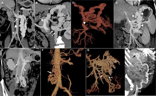
Figure 2 Circuit theory and hemodynamics of portosystemic shunts.
Notes: (A) The circuit theory of portosystemic shunt formation. (B) Demonstration of the shunt hemodynamics and the potential sites of occlusion. Adapted from Kim M, Lee K-Y. Understanding the pathophysiology of portosystemic shunt by simulation using an electric circuit. Biomed Res Int. 2016;2016(81):ID 2097363.Citation7 Copyright © 2016 Moonhwan Kim and Keon-Young Lee. Creative Commons license available at: https://creativecommons.org/licenses/by/4.0/legalcode.
Abbreviations: IVC, inferior vena cava; LGV, left gastric (or coronary) vein; LRV, left renal vein; PGV, posterior gastric vein; PV, portal vein; SGV, short gastric veins; SMV, superior mesenteric vein; SV, splenic vein.
Abbreviations: IVC, inferior vena cava; LGV, left gastric (or coronary) vein; LRV, left renal vein; PGV, posterior gastric vein; PV, portal vein; SGV, short gastric veins; SMV, superior mesenteric vein; SV, splenic vein.
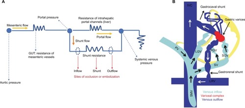
Figure 3 Interventional management of portosystemic shunt syndrome.
Notes: (A) Fluoroscopic image demonstrating of mixture of foam sclerosant and gelfoam slurry within a lienorenal shunt after balloon occlusion (white arrow) through guidewire sheath kept at origin of shunt (black arrow). (B) BRTO (black arrow) of gastrolienorenal shunt with the occlusion balloon catheter in situ (white arrow). (C) Percutaneous transhepatic CAATO of posterior gastric vein (arrow). (D) Multiple coils placed within the origin of the posterior gastric vein, leading to occlusion of the shunt (white arrow shown in E). (F) In the first approach of management of dilated PUV, direct puncturing of the PUV through the anterior abdominal wall (retrograde approach; arrow, guiding catheter) is performed and (G) opacification of the portal system is noted (dotted arrow, left portal vein). (H) In addition, plug- assisted occlusion (arrow) of the PUV through retrograde approach is performed. (I) In the alternative method for occluding the PUV (arrowhead, guiding catheter; solid arrow, coils; dashed arrow, left portal vein) an antegrade approach is utilized.
Abbreviations: BRTO, balloon assisted retrograde transvenous occlusion; CAATO, coil-assisted antegrade occlusion; PUV, paraumbilical vein.
Abbreviations: BRTO, balloon assisted retrograde transvenous occlusion; CAATO, coil-assisted antegrade occlusion; PUV, paraumbilical vein.
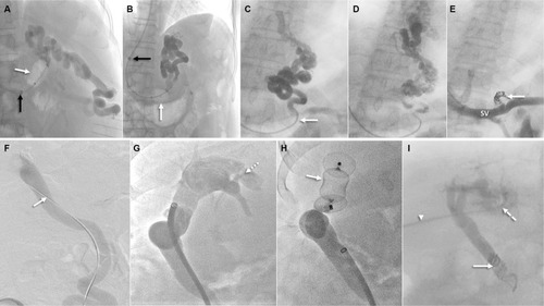
Figure 4 Balloon-assisted retrograde transvenous obliteration of lienorenal shunt.
Notes: (A) Fluoroscopic images demonstrating stasis of the mixture of foam sclerosant and lipiodol within the lienorenal shunt (asterisks) with the long curved vascular access sheath (black arrow) and occlusion balloon catheter in situ (white arrow). (B) Extensive opacification of the tortuous shunt is noted (asterisks) post-sclerosant injection. (C) One hour after the sclerosant injection and opacification (asterisks) lipiodol is seen staining the walls of the shunt (white arrows).
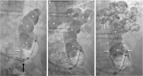
Figure 5 CARTO of mesorenal shunt in a 62-year-old male with refractory HE.
Notes: Coronal-oblique MIP image (A) demonstrates a tortuous mesorenal shunt (arrow, afferent from superior mesenteric vein; arrowhead, efferent into left renal vein). Occlusion venogram (B) demonstrates near-complete stasis of contrast within the shunt. Multiple coils (white arrow) have been utilized for shunt occlusion.
Abbreviations: CARTO, coil-assisted retrograde transvenous obliteration; HE, hepatic encephalopathy; LRV, left renal vein; MIP, maximum intensity projection.
Abbreviations: CARTO, coil-assisted retrograde transvenous obliteration; HE, hepatic encephalopathy; LRV, left renal vein; MIP, maximum intensity projection.
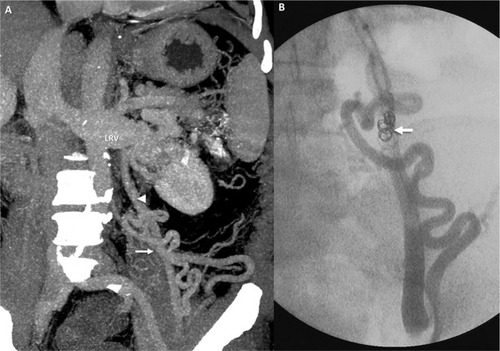
Figure 6 BRTO of a gastrolienorenal shunt in a 48-year-old male.
Notes: Coronal-oblique (A) and axial (B) MIP images demonstrate the gastrolienorenal shunt (encircled in A) and gastric mucosal collaterals (encircled in B). Fluoroscopic image (C) shows shunt (asterisks) with long curved vascular sheath (black arrow) and occlusion balloon catheter in situ (white arrow). Post-procedural CT images (D and E) demonstrate complete obliteration of the shunt and gastric collaterals, respectively (encircled).
Abbreviations: BRTO, balloon-assisted retrograde transvenous occlusion; MIP, maximum intensity projection.
Abbreviations: BRTO, balloon-assisted retrograde transvenous occlusion; MIP, maximum intensity projection.
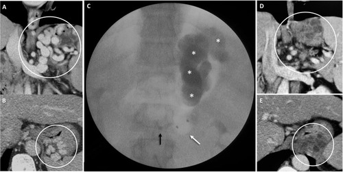
Table 1 Major studies on shunt embolization for recurrent or refractory hepatic encephalopathy