Figures & data
Figure 1 The implantation procedure of LBBaP. (A) Fluoroscopic image of 4-pole RV electrode and axillary vein position, RBB potential were recorded (white circle shows). (B) HB potential (white circle shows) was identified at IEGM and fluoroscopic image of the 3830 lead and sheath position were recorded as a mark. (C) PVC (white circle shows) emerging from endometrial surface of the left ventricular septum was observed during the lead implantation and fluoroscopic image of LBB area was confirmed.
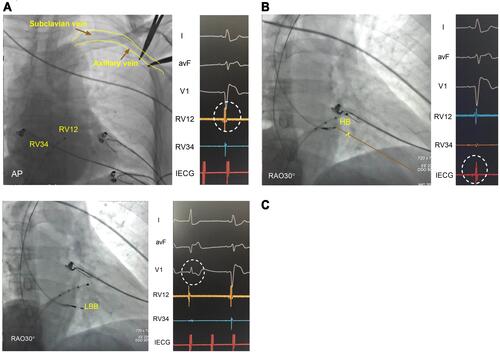
Figure 2 Twelve-lead electrocardiogram and electrogram during LBBaP. (A) Intrinsic rhythm in LBBaP. The change in the notch morphology in lead V 1 (red arrow) during rotating the lead from the right side to the left side of the septum (B-D). (E) Left bundle branch potential. The S-PLVAT in lead V5 with low and high output (F and G).
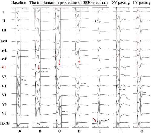
Figure 3 Postoperative images of LBBaP (A and B) and RVSP (D and E), contrast injection through the sheath in LBBaP (C) and RVSP (F).
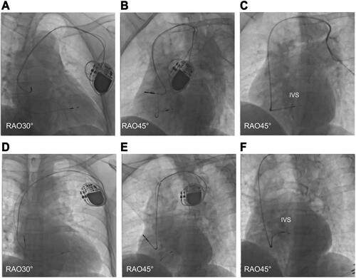
Table 1 Baseline Patient Characteristics and Procedure Outcomes
Table 2 Comparison of QRSd and Echocardiographic Parameters Between the LBBaP and RVSP Groups Before and After Pacemaker Implantation
Table 3 Changes in Pacing Parameters at Follow-Ups
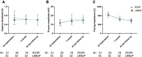
Figure 4 Change trend of Capture threshold (A), R-wave amplitude (B), and Pacing impedance (C) between two groups at implantation, 1 month and at last follow-up. LBBaP, left bundle branch area pacing; and RVSP, right ventricular septum pacing.