Figures & data
Scheme 1 Synergistic combination of sodium aescinate stabilized polymer-free twin-like nanoparticles to reverse paclitaxel resistance. (A) Aes was utilized to stabilize hydrophobic PTX and FKA to form polymer-free twin-like PTX-A NPs and FKA-A NPs. (B) With the aid of Aes, these two drugs could accumulate in tumor tissue via passive targeting and be efficiently taken up by PTX-resistant lung cancer (A549/T) cells, synergistic effects and reversed PTX resistance were achieved by combination of PTX-A NPs and FKA-A NPs via inhibiting P-gp expression in tumor cells.
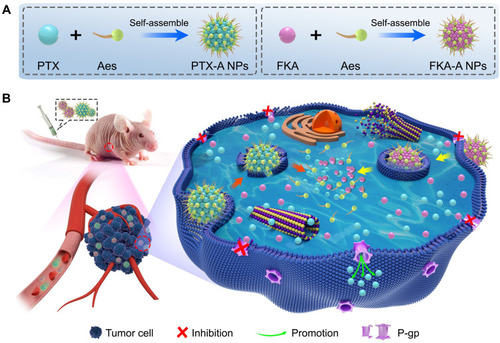
Figure 1 (A) Characterizations of PTX-A NPs with different ratio of PTX to Aes and FKA-A NPs with different ratio of FKA to Aes. (B and C) TEM images and appearance of the optimized nanoparticles. “–” represented that the resulting solutions formed precipitation within 24 h.
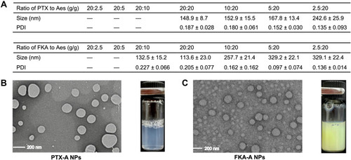
Figure 2 (A) DLS curves at different concentrations and (B) zeta potential of optimized PTX-A NPs. (C) DLS curves at different concentrations and (D) zeta potential of optimized FKA-A NPs.
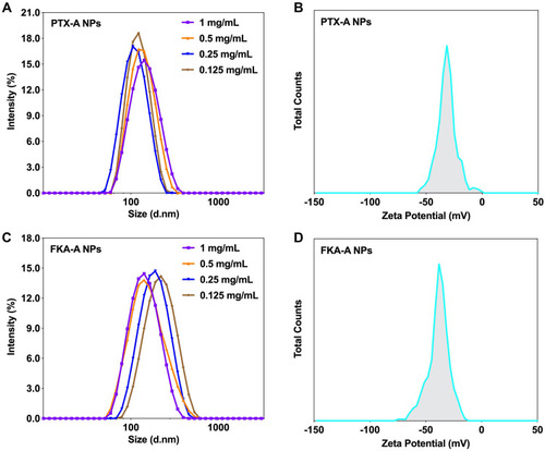
Figure 3 X-ray diffraction diagrams of PTX (A), FKA (B), Aes (C), PTX-A NPs (D) and FKA-A NPs (E).

Figure 4 (A) The UV spectrum of PTX, PTX-A NPs, Aes and PTX/Aes solution. (B) The UV spectrum of PTX, Aes and PTX/Aes in different solvent. (C) The UV spectrum of FKA, FKA-A NPs, Aes and FKA/Aes solution. (D) The UV spectrum of FKA, Aes and FKA/Aes in different solvent.
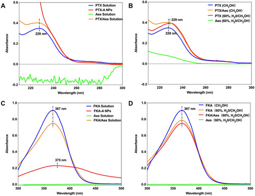
Figure 5 In vitro release behavior of PTX-A NPs (A) and FKA-A NPs (B).
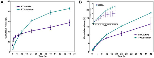
Figure 6 (A) The self-assembly process of FKA-A NPs from 0 to 100 ns. Aes was colored in blue with hydrophilic part represented by lime isosurfaces. FKA was colored in yellow. (B) The self-assembly process of PTX-A NPs from 0 to 100 ns. Aes was colored in blue with hydrophilic part represented by lime isosurfaces and PTX were colored in yellow. The time evolution of the overall RMSD of the FKA and Aes as well as PTX and Aes were also provided. (C) Structure of the self-assembled FKA-A NPs at 100 ns. (D) Structure of the self-assembled PTX-A NPs at 100 ns.
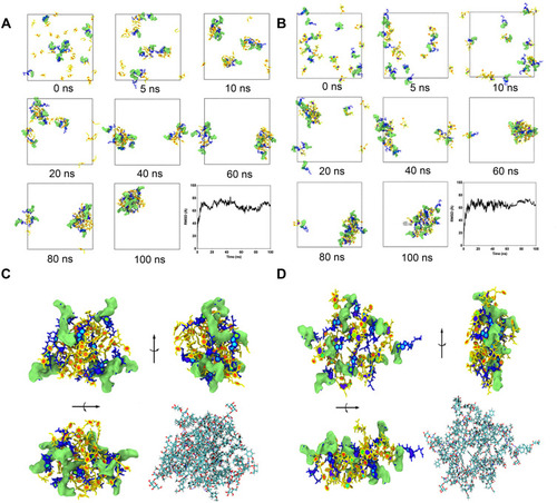
Figure 7 (A) Representative fluorescence microscope images of cellular uptake of C6-A NPs in A549/T cells at different times. (B) Fluorescence spectra of cellular uptake of C6-A NPs in A549/T cells. (C) Internalization rates of C6-A NPs analyzed by flow cytometry. ***p<0.001 vs free C6 (n = 3). (D) Cytotoxicity of FKA, PTX, FKA+PTX in A549/T cells. (E) Cytotoxicity of PTX-A NPs, FKA-A NPs and PTX-A NPs + FKA-A NPs in A549/T cells.
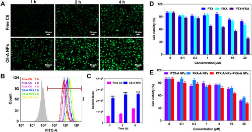
Figure 8 (A) Flow cytometry analysis for apoptosis of A549/T cells induced by Aes, PTX+FKA and PTX-A NPs + FKA-A NPs. *p <0.05 vs control, (n = 3). (B) Cell cycle distribution histograms of A549/T treated with Aes, PTX+FKA and PTX-A NPs + FKA-A NPs. *p <0.05 vs control, (n = 3).
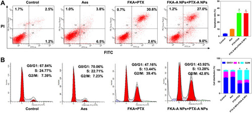
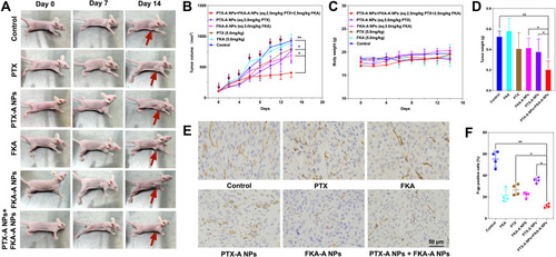
Figure 9 Combination of PTX-A NPs and FKA-A NPs exhibited potent antitumor activity in PTX-resistant homograft mice. (A-B) Antitumor activities in A549/T bearing female BALB/c mice. The red arrow represents the location of the tumor. *p < 0.05 vs PTX-A NPs or FKA-A NPs, **p < 0.01 vs control group (n = 5). (C) Changes of mouse body weight over the experiment. (D) Average tumor mass isolated from the mice of each experimental group. **p < 0.01, *p < 0.05 (n = 5). (E) Immunohistochemical analysis of tumor tissues treated with various treatments. Tumor sections were evaluated for P-gp expression using an rabbit anti-human P-gp antibody (magnification ×400). (F) P-gp-positive rates in the six groups, **p < 0.01, *p < 0.05 (n = 4).