Figures & data
Figure 1 Full view of fabrication process of polymer microneedle patch. The patch was fabricated by casting polymer solution in mold, cross-linking to form needles through freeze-thawing, detaching, and drying.
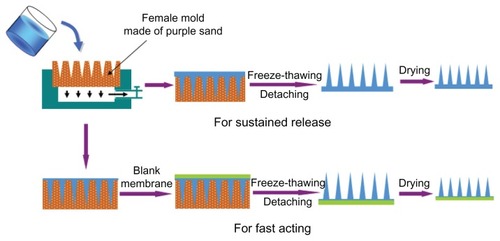
Figure 2 Fabrication of male mold of microneedles: (A) a single finished hexagonal steel stick; (B) thousands of steel sticks fixed into a steel bucket to form the core of the male mold; (C) the male mold with purple sand spreading smoothly; (D) the female mold prepared using the male mold.
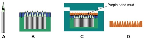
Figure 3 Drying process of microneedle patch. In the first step, the patch was dried with shrinking to adjust size and distance of needles. In the following step, the patch was completely dried with its size fixed.
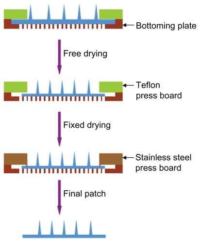
Table 1 Properties of purple-sand female mold calcinated at different temperatures (with calcinating time of 3 hours)
Figure 4 Siphonage of female molds prepared at different temperatures: (A) 940°C; (B) 980°C; (C) 1020°C.
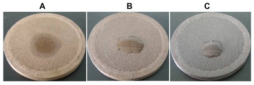
Table 2 Properties of purple-sand female mold calcinated with different times (at 960°C)
Figure 5 Instruments used in microneedle-patch drying: (A) stainless plate with six drying units; (B) Teflon board (press 1) over the drying plate; (C) press 2 made of stainless steel with enough weight to fix microneedle patch.
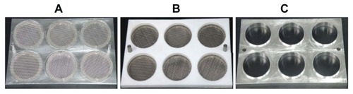
Figure 6 Shrinkage of microneedle patch in free-drying process: (A) effect of relative air humidity; (B) effect of airflow rate.
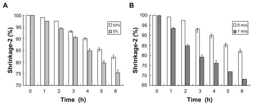
Figure 7 Skin penetration by microneedles: (A) pigskin dyed with trypan blue after microneedle patch removed; (B) micrograph of tissue slice of the pigskin.
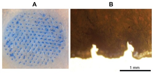
Figure 8 Swelling of microneedles after inserting into human skin: (A) before patching; (B) 1 hour after patching; (C) 3 hours after patching.
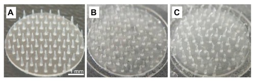
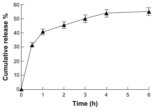
Figure 9 In vitro release profile of insulin from microneedle patches to Franz cells (n = 6).