Figures & data
Figure 1 AFM topography images of: (A) PLGA single layer that was spin coated at 53 × g for 30 seconds. (B) PCL single layer that was spin coated at 53 × g for 30 seconds. (C) Dual layer (PLGA [75:25]–PCL) that was spin coated at 53 × g for 30 seconds. (D) Triple layer (PLGA [65:35]–PLGA [75:25]–PCL) that was spin coated at 53 × g for 30 seconds. The scan size is 2.5 μm × 2.5 μm. (E) Corresponding X cross sections of Figure 1B and C that reveal the dimensions of the holes between the spherulites of PCL single layers and the pore sizes of PLGA–PCL dual layers, respectively.
Abbreviations: PLGA, poly (DL-lactide-co-glycolide); PCL, polycaprolactone.
![Figure 1 AFM topography images of: (A) PLGA single layer that was spin coated at 53 × g for 30 seconds. (B) PCL single layer that was spin coated at 53 × g for 30 seconds. (C) Dual layer (PLGA [75:25]–PCL) that was spin coated at 53 × g for 30 seconds. (D) Triple layer (PLGA [65:35]–PLGA [75:25]–PCL) that was spin coated at 53 × g for 30 seconds. The scan size is 2.5 μm × 2.5 μm. (E) Corresponding X cross sections of Figure 1B and C that reveal the dimensions of the holes between the spherulites of PCL single layers and the pore sizes of PLGA–PCL dual layers, respectively.Abbreviations: PLGA, poly (DL-lactide-co-glycolide); PCL, polycaprolactone.](/cms/asset/ab4183f6-19f6-445a-ae25-f42ca490d201/dijn_a_31185_f0001_c.jpg)
Table 1 AFM data of the surface characteristics of the drug-free polymeric layers
Table 2 AFM data of triple layers (PLGA [65:35]–PLGA [75:25]–PCL) fabricated under variable experimental conditions
Figure 2 AFM topography images of the triple layer (PLGA [65:35]–PLGA [75:25]–PCL) fabricated under variable experimental conditions. (A) Polymer concentration of 10 mg mL−1, spin coated at 24 × g for 30 seconds; (B) polymer concentration of 10 mg mL−1, spin coated at 53 × g for 30 seconds; and (C) polymer concentration of 5 mg mL−1, spin coated at 24 × g for 30 seconds.
Note: The scan size is 10 μm × 10 μm.
Abbreviations: PLGA, poly (DL-lactide-co-glycolide); PCL, polycaprolactone.
![Figure 2 AFM topography images of the triple layer (PLGA [65:35]–PLGA [75:25]–PCL) fabricated under variable experimental conditions. (A) Polymer concentration of 10 mg mL−1, spin coated at 24 × g for 30 seconds; (B) polymer concentration of 10 mg mL−1, spin coated at 53 × g for 30 seconds; and (C) polymer concentration of 5 mg mL−1, spin coated at 24 × g for 30 seconds.Note: The scan size is 10 μm × 10 μm.Abbreviations: PLGA, poly (DL-lactide-co-glycolide); PCL, polycaprolactone.](/cms/asset/165536cf-c919-4e2e-ba53-ef747ade15db/dijn_a_31185_f0002_c.jpg)
Figure 3 The experimental pseudodielectric functions (symbols) and the corresponding simulated ones (solid lines) determined by the use of best-fit results or the single-layer polymeric films: (A) PLGA 75:25–c-Si, (B) PCL–c-Si, (C) the dual-layer PLGA (PLGA [75:25]–PCL-c-Si), and (D) the triple-layer (PLGA [65:35]–PLGA [75:25]–PCL-c-Si).
Note: The insets in the figures show the geometrical model, which was applied in each case, and the respective thicknesses of the polymeric films derived by the fitting analysis.
Abbreviations: PLGA, poly (DL-lactide-co-glycolide); PCL, polycaprolactone; Si, silicon.
![Figure 3 The experimental pseudodielectric functions (symbols) and the corresponding simulated ones (solid lines) determined by the use of best-fit results or the single-layer polymeric films: (A) PLGA 75:25–c-Si, (B) PCL–c-Si, (C) the dual-layer PLGA (PLGA [75:25]–PCL-c-Si), and (D) the triple-layer (PLGA [65:35]–PLGA [75:25]–PCL-c-Si).Note: The insets in the figures show the geometrical model, which was applied in each case, and the respective thicknesses of the polymeric films derived by the fitting analysis.Abbreviations: PLGA, poly (DL-lactide-co-glycolide); PCL, polycaprolactone; Si, silicon.](/cms/asset/69d7ad56-dd2e-4c5c-8e4e-93d70aa7d1d3/dijn_a_31185_f0003_c.jpg)
Figure 4 The real part of the bulk complex refractive index n calculated using best-fit parameters of the SE data analysis for the single-layer polymeric films PLGA 75:25 and PCL, the PLGA 75:25 and PCL from the dual-layer film, and the PLGA 65:35 and PCL from the triple-layer film.
Abbreviations: SE, spectroscopic ellipsometry; PLGA, poly (DL-lactide-co-glycolide); PCL, polycaprolactone.
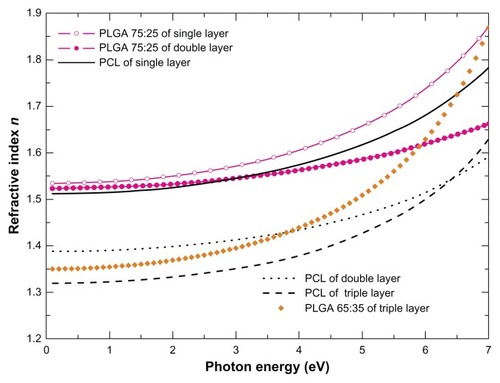
Table 3 AFM data of platelet adhesion onto drug-free and drug-loaded triple layer (PLGA [65:35]–PLGA [75:25]–PCL)
Figure 5 AFM topography images of the triple layer (PLGA [65:35]–PLGA [75:25]–PCL) loaded with dipyridamole: (A) as fabricated by spin coating at 53 × g for 30 seconds and (B) after its degradation in PBS solution for 15 minutes.
Note: The scan size is 2.5 μm × 2.5 μm.
Abbreviations: AFM, atomic force microscopy; PLGA, poly (DL-lactide-co-glycolide); PCL, polycaprolactone; PBS, phosphate buffered saline
![Figure 5 AFM topography images of the triple layer (PLGA [65:35]–PLGA [75:25]–PCL) loaded with dipyridamole: (A) as fabricated by spin coating at 53 × g for 30 seconds and (B) after its degradation in PBS solution for 15 minutes.Note: The scan size is 2.5 μm × 2.5 μm.Abbreviations: AFM, atomic force microscopy; PLGA, poly (DL-lactide-co-glycolide); PCL, polycaprolactone; PBS, phosphate buffered saline](/cms/asset/05a48cb7-a55e-4bc9-9c6c-30c092a6be48/dijn_a_31185_f0005_c.jpg)
Figure 6 AFM topography images of platelets onto (A and B) drug-free and (C and D) dipyridamole-loaded triple layers (PLGA [65:35]–PLGA [75:25]–PCL). Both samples were spin coated at 53 × g for 30 seconds. (A) drug-free sample after 1 hour of platelet adhesion; (B) drug-free sample after 2 hours of platelet adhesion; (C) drug-loaded sample after 1 hour of platelet adhesion; and (D) drug-loaded sample after 2 hours of platelet adhesion with a typical cross section (inset).
Note: The scan size is 20 μm × 20 μm.
Abbreviations: AFM, atomic force microscopy; PLGA, poly (DL-lactide-co-glycolide); PCL, polycaprolactone.
![Figure 6 AFM topography images of platelets onto (A and B) drug-free and (C and D) dipyridamole-loaded triple layers (PLGA [65:35]–PLGA [75:25]–PCL). Both samples were spin coated at 53 × g for 30 seconds. (A) drug-free sample after 1 hour of platelet adhesion; (B) drug-free sample after 2 hours of platelet adhesion; (C) drug-loaded sample after 1 hour of platelet adhesion; and (D) drug-loaded sample after 2 hours of platelet adhesion with a typical cross section (inset).Note: The scan size is 20 μm × 20 μm.Abbreviations: AFM, atomic force microscopy; PLGA, poly (DL-lactide-co-glycolide); PCL, polycaprolactone.](/cms/asset/1d6b66ae-4fca-4c34-a5df-ffe9812c278c/dijn_a_31185_f0006_c.jpg)
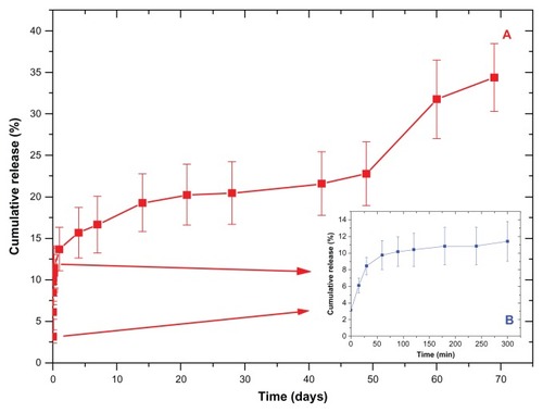
Figure 7 The dipyridamole cumulative release profiles from the three layer samples.
Note: The inset graph depicts the burst effect that occurs during the first 5 hours.