Figures & data
Figure 1 Hierarchical bone configuration at varying size scales. The cortical bone microstructure is made up of osteons with lamellae Haversian channels, while the structural units at the nanoscale are collagen threads having rolls of mineralized collagen fibrils.
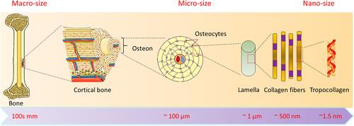
Table 1 Different Salts of Calcium Phosphate
Figure 2 Hydroxyapatite crystal structure, (A) top view and (B) side view. Dashed lines represent one line.
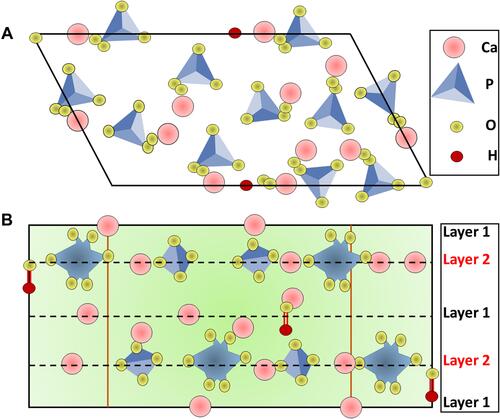
Table 2 Techniques for the Synthesis of Hydroxyapatite Nanomaterials and Their Features
Figure 3 Hydroxyapatite characterization by (A) FTIR spectrum of HA-NMs calcined at 400°C (a and b), while (c) signifies IR spectra of HA at different temperature. Figure A reprinted with permission from Elsevier, from: Kalita SJ, Verma S. Nanocrystalline hydroxyapatite bioceramic using microwave radiation: Synthesis and characterization. Mater Sci Eng C. 2010;30:295–303.Citation65 Copyright © 2010 Elsevier. (B) XPS spectrum showing the presence of Ca, O, P with small amounts of contamination (such as C), (C) TOF-SIMS spectra (a) Positive and (b) negative. Figures B and C reprinted with permission from American Chemical Society, from: Lu HB, Campbell CT, Graham DJ, Ratner BD. Surface characterization of hydroxyapatite and related calcium phosphates by XPS and TOF-SIMS. Anal Chem. 2000;72:2886–2894.Citation66 Copyright © 2000 American Chemical Society. (D) Nitrogen physisorption isotherms and BJH pore size distribution (E) adsorption (F) desorption. Figures D-F reprinted with permission from American Chemical Society, from: Munir MU, Ihsan A, Javed I et al. Controllably biodegradable hydroxyapatite nanostructures for cefazolin delivery against antibacterial resistance. ACS Omega. 2019;4(4):7524–7532.Citation67 Copyright © 2019 American Chemical Society (https://pubs.acs.org/doi/10.1021/acsomega.9b00541; further permissions related to the material excerpted should be directed to the ACS).
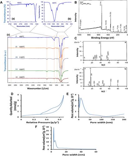
Figure 4 Hydroxyapatite nanomaterials characterization (A) (a) An illustration indicating the synthetic process of hollow mesoporous hydroxyapatite nanoparticles (hmHANP). SEM images of (b) CaCO3 nanoparticles, (c) CaCO3/HA core/shell nanocomposites, (d) hmHANP; TEM images of (e) CaCO3 nanoparticles, (f) CaCO3/HA core/shell nanocomposites, (g) hmHANP (inset: dark-field STEM image). Figure A republished with permission of Royal Society of Chemistry, from: Yang YH, Liu CH, Liang YH, Lin FH, Wu KCW. Hollow mesoporous hydroxyapatite nanoparticles (hmHANPs) with enhanced drug loading and pH-responsive release properties for intracellular drug delivery. J Mater Chem B. 2013;1:2447–2450.,Citation68 copyright © 2013 Royal Society of Chemistry; permission conveyed through Copyright Clearance Center, Inc. (B) XRD pattern of HA-NMs synthesized by hydrothermal treatment at 180 °C for (a) 12, (b) 24, and (c) 48 h. (C) Raman spectra of nanodisks (a) and nanorings (b). Inset shows the deviation of the specific peak. Figures B and C reprinted with permission from the American Chemical Society, from: Nathanael AJ, Hong SI, Mangalaraj D, Ponpandian N, Chen PC. Template-free growth of novel hydroxyapatite nanorings: formation mechanism and their enhanced functional properties. Cryst Growth Des. 2012;12:3565–3574.Citation64 Copyright © 2012 American Chemical Society.
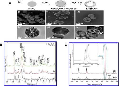
Table 3 Various Methods Applied for the Modification of Hydroxyapatite
Figure 5 Schematic diagram to express the role of hydroxyapatite nanomaterials in drug delivery.
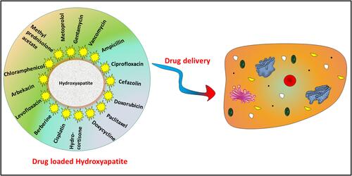
Figure 6 (A) Oriented Immobilization of β-Lactamase and enhanced green fluorescent protein (EGFP) on HA through hydrazine bisphosphonates (HBPs). (B) Immobilization of EGFP and (C) β-lactamase on HA surfaces determined by fluorescence and BCA protein assay, respectively. EGFP and β-lactamase were immobilized on HA surfaces via seven different HBPs (1−7) and by simple adsorption like HA-EGFP and HA-BL, respectively. The corresponding EGFP and β-lactamase are denoted as HA-1-EGFP through HA-7-EGFP and HA-1-BL through HA-7-BL, respectively. HA-EGFP and HA-BL are referred to EGFP and β-lactamase physically adsorbed on HA in the absence of HBP. (* indicates the values are significantly different from others p < 0.05, while ** indicates the values are significantly different from HA-1-BL and HA-5-BL p < 0.05). Figures A-C reprinted with permission from American Chemical Society from: Yewle JN, Wei Y, Puleo DA, Daunert S, Bachas LG. Oriented immobilization of proteins on hydroxyapatite surface using bifunctional bisphosphonates as linkers. Biomacromolecules. 2012;13:1742–1749.Citation132 Copyright © 2012 American Chemical Society.
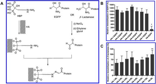
Figure 7 Schematic diagram representing phases of colonization mechanisms anticipated for HA-NMs coating. (A) Adhesion phenomenon starts in the cells by confining anchoring/adhesion spots in micropore surfaces. (B) These cells give response to adjacent hierarchical environment. (C) The growth of filopodia is guided by coating material penetration and resulting formation of nano sized lengthy morphology. Figures A-C reprinted with permission from American Chemical Society from: Nasiri N, Mukherjee S, Panneerselvan A, Nisbet DR, Tricoli A. Optimally hierarchical nanostructured hydroxyapatite coatings for superior prosthesis biointegration. ACS Appl Mater Interfaces. 2018;10(29):24840–24849.Citation142 Copyright © 2018 American Chemical Society. (D) Mixed state including (i) PLGA rich state (ii) HA rich state (E) Grafting state (i) short chain/large number (ii) long chain/small number (F) Tensile strength measurements of PLGA-HA and interaction evaluation of tensile strength with and without PLGA-HA composite. Figures D-F reprinted with permission from Elsevier from: Park JW, Hwang JU, Back JH et al. High strength PLGA/Hydroxyapatite composites with tunable surface structure using PLGA direct grafting method for orthopedic implants. Compos Part B Eng. 2019;178:107449.Citation160 Copyright © 2019 Elsevier.
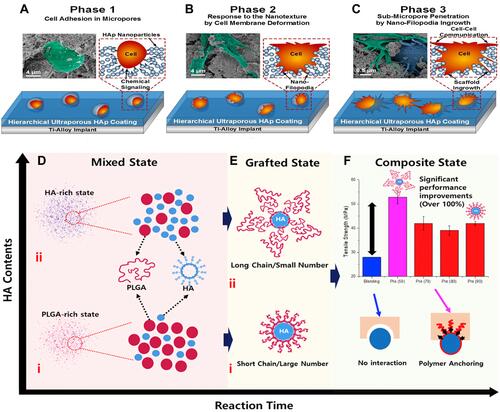
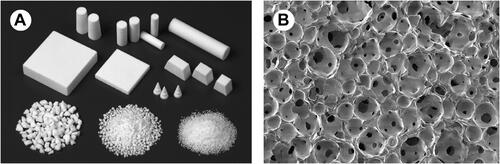
Figure 8 Porous HA ceramics (A) macroscopic image (B) SEM image representing spherical pores of diameter 100–200 μm are unified by pores with diameter 10–80 μm. Republished with permission from The Royal Society from: Yoshikawa H, Tamai N, Murase T, Myoui A. Interconnected porous hydroxyapatite ceramics for bone tissue engineering. J R Soc Interface. 2009;6(suppl_3):S341-S348.Citation192 Copyright © 2009; permission conveyed through Copyright Clearance Center, Inc.