Figures & data
Figure 1 Cortical bone trajectory (CBT) screw placement under the guidance of 3D-printed templates and cement injection.
Notes: (A) The templates were positioned correctly in close contact with the posterior bony area after all posterior soft tissue was removed from the cadaveric specimens. (B) An electric drill with a bit 2.5 mm in diameter was driven into the vertebra along the direction of the template’s channel. (C) A Kirschner wire was inserted in the needle lumen, and a cannulated screw tap 4.5 mm in outer diameter was used for tapping according to the guidance of the wire. (D) A screw was inserted following the CBT trajectory. (E) The cement was injected in the selected screws by a push rod.
Abbreviation: CBT, cortical bone trajectory.
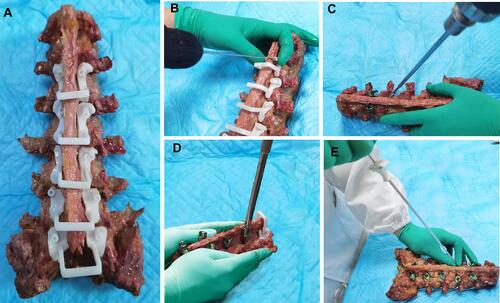
Table 1 Information and Characterization of Cadaver Specimens
Figure 2 Radiological evaluation of cement-augmented cortical bone trajectory (CBT) screws.
Notes: (A) A schematic revealing the design of a 3D-printed template according to the reconstruction from computed tomography data. (B) X-ray anteroposterior and lateral views of the specimen after inserting the screws and cement augmentation. (C) X-ray axial view of the cement mass. (D) The diagram of the CBT screw and the demarcation point that bisects the first third of the whole screw. (E) The total volume of bone cement was divided into two parts; the green part is the rear volume and the blue part is the front volume.
Abbreviations: CPN, calcium phosphate–based nanocomposite; PMMA, polymethylmethacrylate.
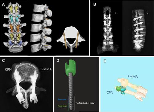
Figure 3 Biomechanical testing of cemented cortical bone trajectory screws.
Notes: (A) torsion test and (B) axial pullout test.
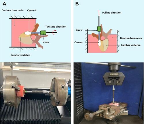
Figure 4 The results of the setting time and rheological properties.
Notes: (A) The setting times of CPN and PMMA; CPN: n = 5, PMMA: n = 5 (B) The rheological properties of CPN. *P < 0.05 vs the PMMA group.
Abbreviations: CPN, calcium phosphate–based nanocomposite; PMMA, polymethylmethacrylate.
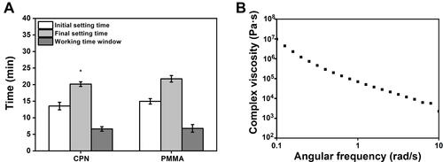
Figure 5 The results of compressive tests.
Notes: (A) Typical stress–strain curves of CPN and PMMA and (B) average compressive strength of CPN and PMMA.
Abbreviations: CPN, calcium phosphate–based nanocomposite; PMMA, polymethylmethacrylate.
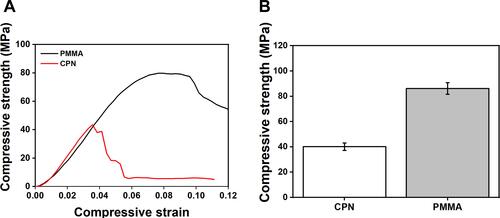
Figure 6 Results of biomechanical tests.
Notes: (A) Typical torque–angle curves of the torsion tests with different augmentation materials. (B) Typical Fmax–displacement curves of the pullout tests with different augmentation materials. (C) Statistical results of the average maximal torque and (D) average maximal pullout force of cortical bone trajectory screws augmented by different cements. *P < 0.05 vs the control group.
Abbreviations: CPN, calcium phosphate–based nanocomposite; PMMA, polymethylmethacrylate.
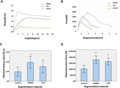
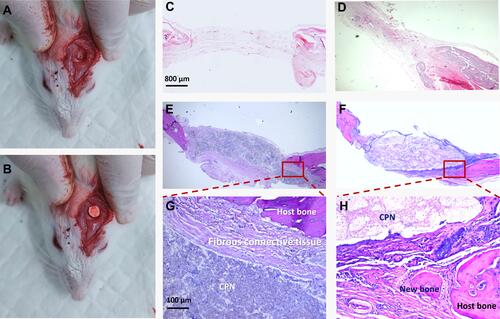
Figure 7 Histological analysis of the calcium phosphate–based nanocomposite (CPN) after implantation in a rat cranial defect model.
Notes: (A) A rat critical-size cranial defect model; (B) CPN sample (volume = 28.26 mm3) implantation; (C) Blank control at 4 weeks (scale bar=800μm); (D) Blank control at 12 weeks (scale bar=800μm); (E) The boundary of CPN was smooth after 4 weeks (scale bar=800μm); (F) The CPN partly degraded and bone ingrowth was observed at 12 weeks (scale bar=800μm). (G) The high-magnification image of E (scale bar=100μm); (H) The high-magnification image of F (scale bar=100μm); The red boxes show the condition of osseointegration and CPN biodegradation on the bone-cement interface.
Abbreviation: CPN, calcium phosphate–based nanocomposite.