Figures & data
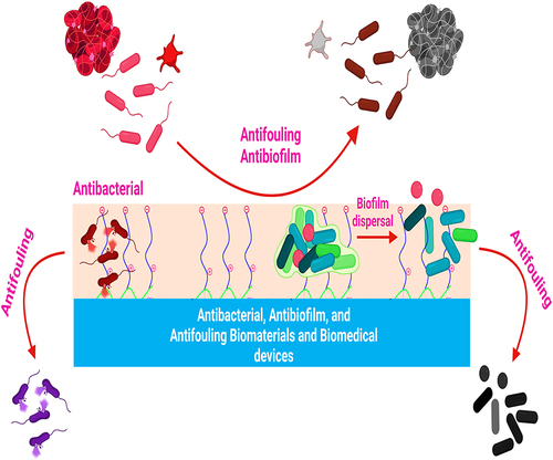
Figure 1 Pathogenic microbial biofilms contaminated biomaterials and biomedical devices induced infections.
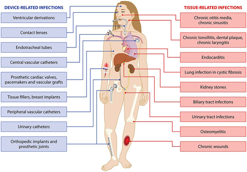
Figure 2 Staphylococcus aureus adherence to the surface of biomaterials and biomedical devices.
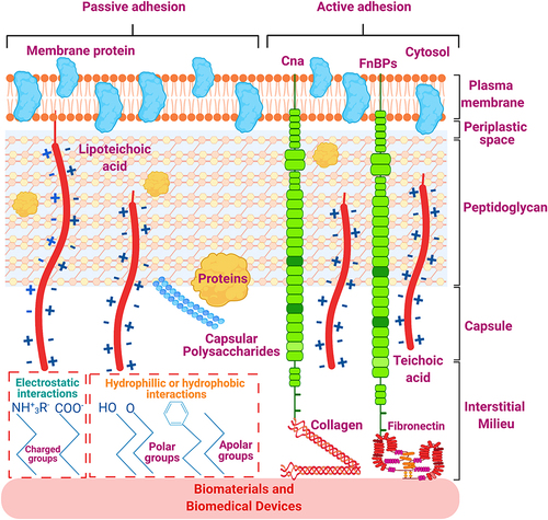
Figure 3 Transitions in the development of a biofilm.
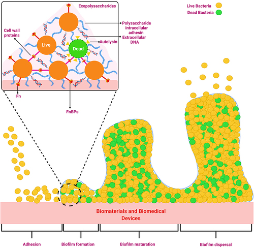
Figure 4 Biofilm formation on the biomedical device (catheter) mediated by conditioning film.
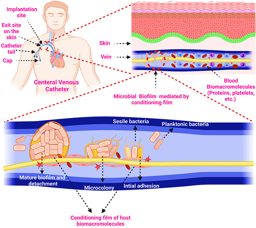
Figure 5 Schematic illustration of the biofouling of biomaterials and biomedical devices.
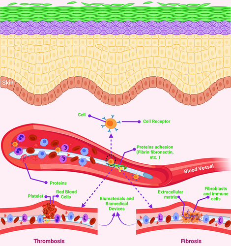
Figure 6 Heparin-induced thrombocytopenia pathogenicity.
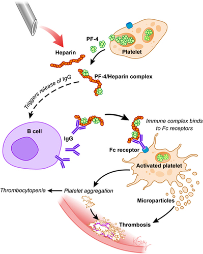
Figure 7 Biomaterial’s infection prevention strategies.
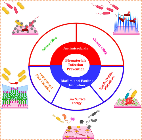
Figure 8 (A) The three-step method of (i) anodic oxidation to produce the TiO2 nanotubes array, (ii) plasma immersion ion implantation to embed Ag nanoparticles into the TiO2 nanotubes, and (iii) vacuum extraction to loading vancomycin into the TiO2 nanotubes is shown schematically; (B) antibacterial activity in the bacteria/cells coculture model: SEM (scanning electron microscope) morphologies of bacteria and fibroblasts linked to the four samples. The photographs below are magnified more than the regions indicated by the red boxes. The bacteria are denoted by the blue arrow, whereas the green arrow marks the fibroblast; (C) fluorescence pictures of fibroblasts stained with DAPI (4′,6-diamidino-2-phenylindole) (blue) and TRITC (Tetramethylrhodamine isothiocyanate)-phalloidin (red) on four samples; (D) surface covers four distinct surfaces following three days of fibroblast cell attachment, spreading, and maturation (**P < 0.01, ***P < 0.001.); (E) schematic representation of the bacteria, fibroblasts, and sample processes. In vivo assessment of peri-implant soft tissues in four groups; (F) X-ray pictures of rabbits 15 days after surgery with different implants. The red oval indicates soft-tissue swelling, and groups NT-V and NT-Ag-V have little or no infectious symptoms; (G) inflammation of the peri-implant soft tissues was seen in all four groups; (H) gross scores of inflammation in the peri-implant soft tissues in four groups (***P < 0.001); (I) bacterial survival in soft tissues around the washer (*P < 0.05, **P < 0.01, ***P < 0.001); (J) a schematic depicting the antibacterial properties of the proposed surface, which has release-killing, contact-killing, and trap-killing capabilities; and (K) illustration depicting potential antibacterial and antibiofilm strategies in a concurrent cell-bacteria system on the titanium surface.
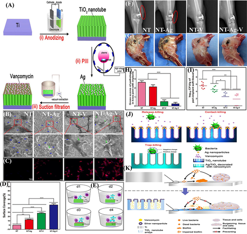
Figure 9 (A) Schematic demonstration for Hep (heparin) immobilization on SR (silicone rubber) followed by NO (nitric oxide) donor SNAP (S-nitroso-N-acetyl penicillamine) impregnation by swelling, resulting in a heparinized NO-releasing surface; (B) S. aureus adhesion; and (C) platelet adhesion on unmodified SR, SR modified only with Hep, SR modified only with SNAP, and SR modified with Hep and SNAP; and (D) photograph display Hep–NO–SR catheter tubes after four hours in an extracorporeal circuit model showing minimal thrombogenesis.
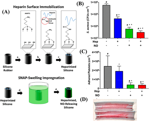
Figure 10 (A) Schematic presentation for the synthesis of PCBDA@AgNPs; (B) PCBDA@AgNPs immobilization on amino-modified cotton gauze; and (C) in vivo wound healing with the PCBDA@AgNPs-CG dressing.
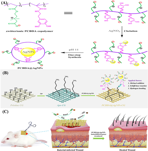
Figure 11 (A) antibacterial and antiadhesion modes of action of the contact killing strategy presented by coated non-releasable bactericidal molecules on the Titanium implant surface. Here APTES is (3-aminopropyl) triethoxysilane. Schematic presentation of antibacterial and antiadhesion performances of (B) bare dental appliance and coated with (C) polyethylene glycol (PEG) and (D) a combination of chitosan (cs) and PEG.
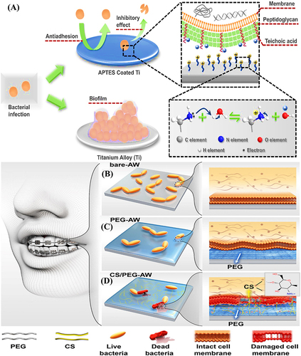
Figure 12 (A) A schematic representation of the antibacterial and antibiofouling properties of silicone rubber tubes (a commonly used catheter material) coated with copolymers; rat implanted with (B and C) pristine PDMS (left) and g-PEG45-b-AMP coated PDMS (right) at 0 and 5th day, respectively; (D and E) rat images after implants removal for antiadhesion test against bacterial adhesion at 5th day; (F) Log CFU/implant; (G) representative colonies images of E. coli isolated from both implants; and (H) SEM images of adhered bacteria on both implants. (I) schematic presentation for the molecular structure and effects of PU-DMH; (J) schematic demonstration for the antibacterial performance evaluation under flow conditions; (K) confocal laser scanning microscopic images after circulating experiment; and (L) S. aureus density on PU and PU-DMH surfaces.
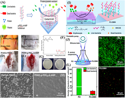
Figure 13 (A) Schematic illustration for the synthesis of zwitterionic antimicrobial Cu metal-phenolic network and coating of contact lens; (B) antibacterial and antifouling mechanism; (C) antiadhesion; (D) antibacterial; and (E) antibiofouling propensities. Reproduced with permission.Citation173 (F) schematic presentation for the medical-grade titanium surface coated with (3-aminopropyl) triethoxysilane. Reproduced with permission.Citation166
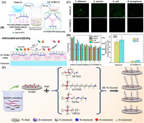
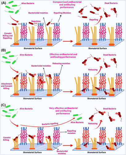
Figure 14 (A) Interaction of co-existing non-releasable bactericidal and fouling repelling moieties with microbials on biomaterial surface; (B) Interaction of co-existing non-releasable bactericidal and fouling releasing moieties with microbials on biomaterial surface; and (C) Interaction of co-existing non-releasable bactericidal and fouling repelling moieties with microbials on the surfaces of biomaterials and biomedical devices.