Figures & data
Figure 1 Schematic description of synaptic interconnections in the simplified computational model of thethalamocortical network.
Abbreviations: IN, interneurons; RTN, reticular thalamic cells; PY, pyramidalneurons; STC, specific thalamic cells; NSTC, nonspecific thalamic cells.
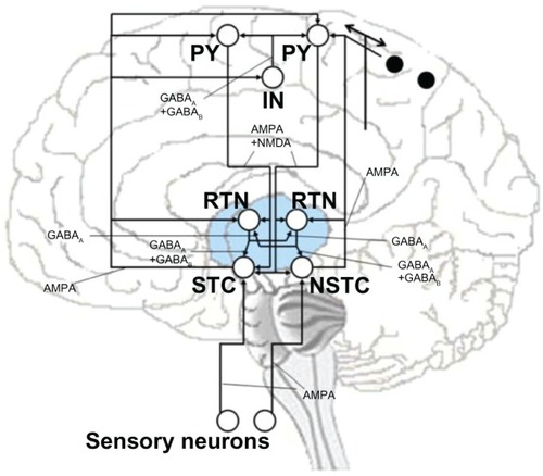
Table 1 Normalized amplitudes of INa before and after cAgNP addition (holding potential−70 mV; depolarization potential −20 mV)
Figure 2 Local application of cAgNP to chromaffin cells. (A) A representativecurrrent-voltage (IV)-curve of a cell before and after application of cAgNP (16 μMol, gray;corresponding control, black). (B) records of INa before and after localapplication of cAgNP after 60 seconds (s) and 120 seconds.
Abbreviations: cAgNP, coated silver nanoparticles; INa, sodium current;ms, milliseconds; mV, millivolt; NP, nanoparticles; pA, picoampere.
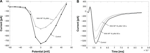
Figure 3 Measured sodium current. Measured sodium current without (A) and with(B) cAgNP (solid lines, holding potential −70 mV, depolarization potential−20 mV), and the curve fits by DE (dashed lines).
Abbreviations: pA, picoampere;INa, sodium current; cAgNP, coated silvernanoparticles; NP, nanoparticles; DE, Differential-Evolution Algorithm.
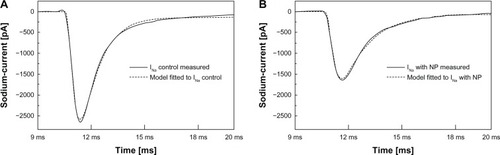
Figure 4 Differences in percentages.
Notes: Differences of model fitted αh, βh,αm, βm, and GNamax between the measured sodiumcurrent with cAgNP in 130 (μMol concentration and the corresponding controls. Theξ.13 (stim–time) is not considered.
Abbreviation: cAgNP, coated silver nanoparticles.
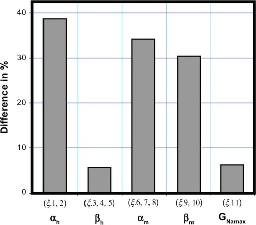
Figure 5 Currents for control. DE fittings (dashed lines) utilizing just the seven identifiedHodgkin–Huxley equation parameters (αh, αm, andβm) and the corresponding electrophysiologically measured currents for control(A) and cAgNP (130 μMol) transfected (B).
Abbreviations: pA, picoampere; INa, sodium current; cAgNP, coated silvernanoparticles; NP, nanoparticles; DE, Differential-Evolution Algorithm; ms, milliseconds.
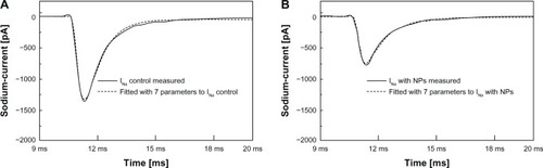
Figure 6 Firing pattern differences of pyramidal neurons.
Note: Differences in firing patterns of PY1, PY2, PY3, and PY4 neuron for 4 secondsbefore and after cAgNP application in thalamic neurons.
Abbreviations: PY, pyramidal neurons; mV, millivolt; cAgNP, coated silvernanoparticles; NP, nanoparticles; ms, milliseconds.
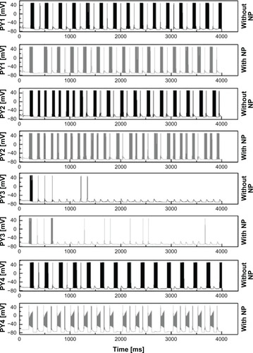
Figure 7 Firing pattern differences in IN, RTN1, RTN, STC, NSTC neurons.
Note: Differences in firing patterns of IN, RTN1, RTN2, STC, and NSTC neuron for 4seconds before and after cAgNP application in RTN and STC neurons.
Abbreviations: IN, interneurons; mV, millivolt; STC, specific thalamic cells; NSTC,nonspecific thalamic cells; RTN, reticular thalamic cells; cAgNP, coated silver nanoparticles; ms,milliseconds, NP, nanoparticles.
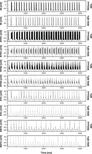
Table 2 Changes in neuronal bursting after cAgNPs application
Table S1 Amplitudes of INa before and after cAgNP addition as total values