Figures & data
Figure 1 The device (A) for robotic antibiotic electroanalysis in 24-well microtiter plates (B).
Notes: The major components are (1) the three-electrode assembly with a pencil lead-WE, a platinum-CE (counterelectrode), and a Ag/AgCl-RE (reference electrode); (2) the microtiter plate platform; (3) the micropositioning stage for vertical movement of the electrode assembly; (4) two micropositioning stages for lateral microtiter plate movement; and (5) (not shown) a potentiostat and a personal computer for system operation and voltammetry.
Abbreviations: CE, counter-electrode; WE, working electrode; RE, reference electrode; WE, working electrode.
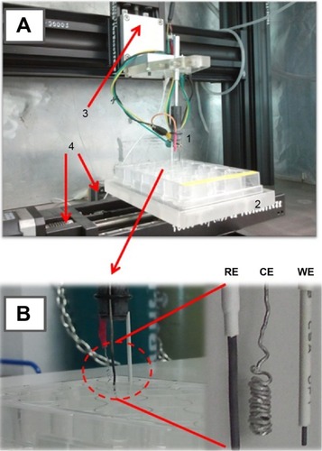
Figure 2 Modification of pencil lead electrodes with carbon nanotubes.
Notes: (A) Schematic of the electrophoretic CNT deposition procedure. At a DC voltage of +1 V for 10 minutes, a well-adhering CNT thin layer is deposited on the PLE, which is then tuned for use as the working electrode for electrochemical drug measurements in the robotic electrochemical workstation. (B) High-resolution SEM image of a randomly selected area on the surface of a CNT-modified PLE (16,000×); the bottom left and right insets are low-resolution SEM images of the CNT-modified (60×) and a bare (50×) PLE, respectively. The area of the zoom shown as part (B) was located within the white box in the left insert.
Abbreviations: PLE, pencil lead electrode; SEM, scanning electron microscopy; CNT, carbon nanotube.
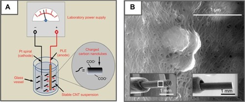
Figure 3 Electrode capacitance determinations for a bare and a CNT-modified PL-WE by cyclic voltammetry in oxygen-free, N2-purged, 0.1 M NaNO3.
Notes: (A) and (C) are the original voltammograms as recorded at seven scan rates in between 20 mV/s and 200 mV/s (from inner to outer traces). Plots (B) and (D) are of the width of the quasi-rectangular CVs at 0.05 V vs Ag/AgCl, against the scan speed. Errors bars in (B) and (D) represent the standard deviation of three measurements; if not clearly visible, the bars happened to be smaller in width than the markers used for data point presentation.
Abbreviations: CNT, carbon nanotube; CV, cyclic voltammetry; PL-WE, pencil lead working electrode.
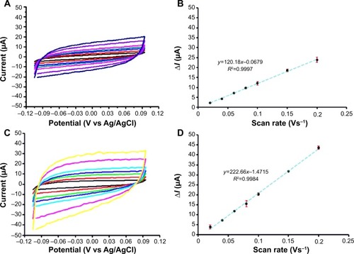
Figure 4 Ferricyanide differential pulse voltammetry with a bare (green) and a CNT-modified (red) pencil lead electrode.
Notes: The concentration of [Fe(CN)6]3− was 1 mM in 0.1 M KCl and the parameters for DPV acquisition were as follows: pulse amplitude 25 mV, pulse width 25 ms and scan speed 20 mV/s.
Abbreviations: CNT, carbon nanotube; DPV, differential pulse voltammetry.
![Figure 4 Ferricyanide differential pulse voltammetry with a bare (green) and a CNT-modified (red) pencil lead electrode.Notes: The concentration of [Fe(CN)6]3− was 1 mM in 0.1 M KCl and the parameters for DPV acquisition were as follows: pulse amplitude 25 mV, pulse width 25 ms and scan speed 20 mV/s.Abbreviations: CNT, carbon nanotube; DPV, differential pulse voltammetry.](/cms/asset/876be0e2-201e-46c5-a1cd-0a03034c06b2/dijn_a_75237_f0004_c.jpg)
Figure 5 DPV of NFX with a bare (black) and a CNT-modified (red) pencil lead working electrode.
Notes: NFX concentration was 10 μM in 0.1 M acetate buffer (pH 4.5)/0.1 M KCl. Parameters for DPV acquisition were as follows: pulse height 25 mV, pulse width 25 ms and scan speed 20 mV/s, with 300 seconds allowed at 0.4 V vs Ag/AgCl before actual DPV initiation.
Abbreviations: CNT, carbon nanotube; DPV, differential pulse voltammetry; NFX, norfloxacin.
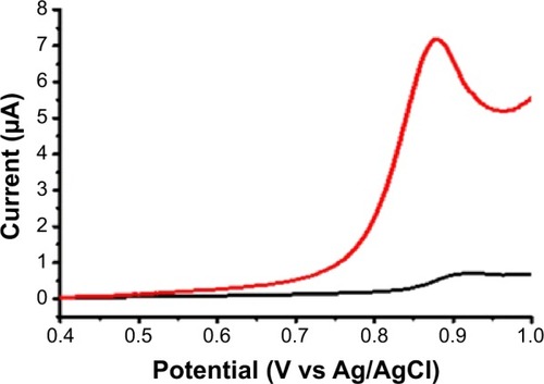
Figure 6 The microtiter plate well loading for robotic voltammetric NFX and CFX stability tests and calibration trials, with CNT-modified pencil lead working electrodes.
Notes: For stability tests, all wells in rows 2, 4, and 6 (including A2) contained sample solution (8 μM for NFX and 50 μM for CFX). For calibration trials, drug levels were between 0 (well A2) and 100 μM (well D6) in 0.1 M acetate (pH 4.5)/0.1 M KCl (NFX) or 0.1 M phosphate (pH 4)/0.1 M KCl (CFX) buffers. Parameters for DPV acquisition in the microtiter plate wells were as follows: pulse height and width 25 mV and 25 ms; scan range and speed 0.4–1.2 V vs RE and 20 mV/s; waiting time before DPV scan initiation 300 seconds (NFX) and 180 seconds (CFX) at 0.4 V vs RE; 25°C. Analytical runs started in well A1 (electrode pretreatment) and finished in well D6 (last sample solution).
Abbreviations: CFX, ciprofloxacin; CNT, carbon nanotube; DPV, differential pulse voltammetry; NFX, norfloxacin; RE, reference electrode.
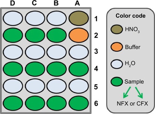
Figure 7 NFX (A) and CFX (B) differential pulse voltammograms from robotic calibration measurement in a 24-well microtiter plate.
Notes: The insets are plots of the peak currents as a function of antibiotic concentration. Electrolyte for in-well DPV was a 0.1 M acetate (pH 4.5)/0.1 M KCl buffer for NFX and a 0.1 M phosphate (pH 4)/0.1 M KCl buffer for CFX. DPV parameters were as follows: pulse height and width 25 mV and 25 ms; scan range and speed 0.4–1.2 V vs. RE and 20 mV/s; waiting time before DPV scan initiation 300 s (NFX) and 180 s (CFX) at 0.4 V vs RE; 25°C. Errors bars in the insets of (A) and (B) represent the standard deviation of three measurements; however, the bars are smaller in width than the markers used for data point presentation and thus do not appear clearly. The peak potentials for the highest concentrations of NFX and CFX are 0.96 and 1.06 V vs Ag/AgCl, respectively.
Abbreviations: CFX, ciprofloxacin; NFX, norfloxacin; DPV, differential pulse voltammetry; RE, reference electrode.
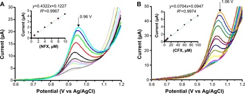
Table 1 Comparison of analytically relevant figures of merit of different electrochemical strategies for the quantitative determination of NFX and CFX
Table 2 Recoveries from robotic microtiter plate voltammetry of NFX and CFX in supplemented prototype, dissolved tablet, and spiked serum samples
Figure 8 Microtiter plate loading as used for robotic voltammetric NFX and CFX quantification trials with CNT-modified pencil lead working electrodes and the standard addition method.
Notes: Electrolyte for in-well DPV was a 0.1 M acetate (pH 4.5)/0.1 M KCl buffer for NFX and a 0.1 M phosphate (pH 4)/0.1 M KCl buffer for CFX. DPV parameters were as follows: pulse height and width 25 mV and 25 ms; scan range and speed 0.4–1.2 V vs. RE and 20 mV/s; waiting time before DPV scan initiation 300 s (NFX) and 180 s (CFX) at 0.4 V vs RE; 25°C. Analytical runs started in well A1 (electrode pretreatment) and ended in well D6 (last sample solution).
Abbreviations: CFX, ciprofloxacin; CNT, carbon nanotube; DPV, differential pulse voltammetry; NFX, norfloxacin; SA, standard addition; RE, reference electrode.
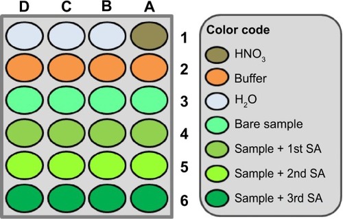
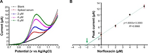
Figure 9 Robotic voltammetric quantification of NFX in spiked human serum samples by the standard addition method.
Notes: A set of four DPVs for buffer alone, a serum sample with 2 mM NFX supplementation, and the solution with three additions of NFX, all acquired in an automated run through a loaded microtiter plate (A). Standard addition curve and linear regression plot (B). Electrolyte for in-well NFX-DPV was a 0.1 M acetate (pH 4.5)/0.1 M KCl buffer. DPV parameters were as follows: pulse height and width 25 mV and 25 ms; scan range and speed 0.4–1.2 V vs. RE and 20 mV/s; waiting time before DPV scan initiation 300 s at 0.4 V vs RE; 25°C. Errors bars in (B) represent the standard deviation of three measurements; however, the error bar for the 4 μM data point is smaller in width than the marker used for data point presentation and thus does not appear clearly. The green arrow points toward the x-axis interception, which represents the actual analyte concentration of the inspected sample.
Abbreviations: DPVs, differential pulse voltammograms; NFX, norfloxacin; RE, reference electrode.