Figures & data
Figure 1 Native radio-cephalic arteriovenous fistula for hemodialysis, with latero-terminal anastomosis.
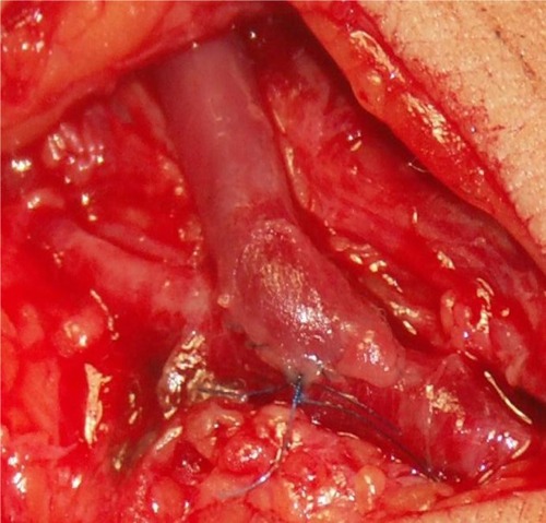
Table 1 Graft materials
Figure 2 Synthetic axillo–axillary graft in polytetrafluoroethylene material.
Table 2 Central vein approaches for dialysis catheters
Figure 3 Photograph of neck in a malnourished patient demonstrating surface anatomy.
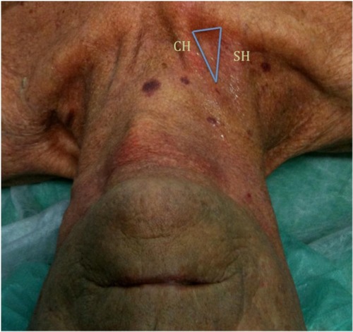
Figure 4 Percentage of variation in anatomical relations between the right and left internal jugular vein (in blue) and common carotid artery (C).
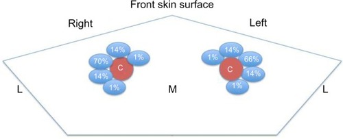
Figure 5 Ultrasound cross-sectional (left) and Doppler ultrasound (right) image of right internal jugular vein (IJV) and carotid artery (CA).
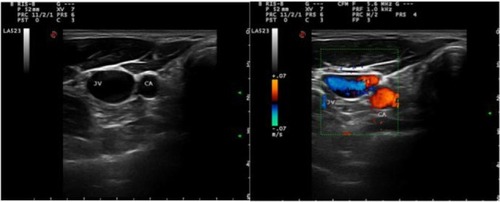
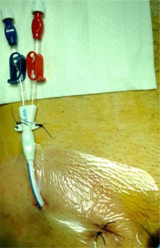
Figure 6 External abdomen location of cuffed tunneled central venous catheters in femoral vein, as a variant of the normal external leg location.