Figures & data
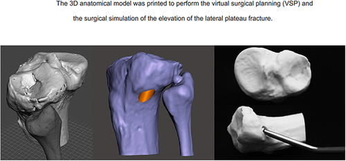
Figure 1 CT images of the distal tibia (A); the 3D anatomical model modeled with CAD software (B); complex tibial plafond fracture treated with circular external fixator (C); outcome of surgical treatment (D).
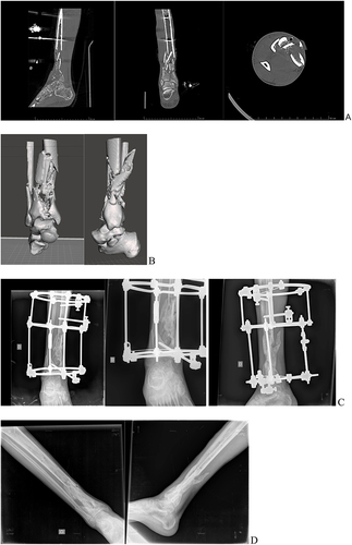
Figure 2 X-ray and CT images showing sinking of the lateral tibial plateau (A); virtual surgical planning and surgical simulation using the 3D printed anatomical model for joint surface elevation (B); intraoperative fluoroscopic image of lateral plateau cartilage elevation (C); outcome of surgical treatment (D).
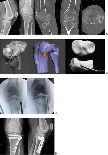
Figure 3 CT images showing nonunion of the coronal femoral lateral condyle fracture - Hoffa’s fracture (A); virtual surgical planning (VSP) performed in CAD software (Meshmixer®) and the 3D printed model used in surgical procedure to reproduce the VSP (B). Outcome of surgical treatment (C).
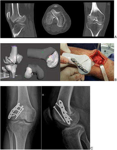
Figure 4 CT images showing C3 right pedicle fracture with a C3-C4 subluxation and a right-side locked facet (A); the 3D model created using Mimics® software to perform VSP (B); the VSP using Meshmixer® software and confirmation the pedicle screw trajectories using 3DSlicer® software (C and D); the personalized drill guide was used to fix pedicle screw (E); outcome of surgical treatment (F).
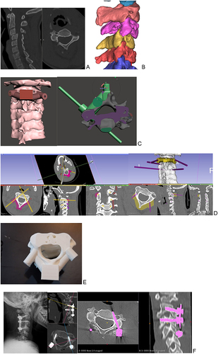
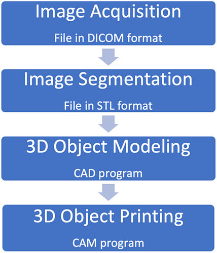
Figure 5 The 3D printing process in the medical area.