Figures & data
Figure 1 (A) Sagittal T2-weighted magnetic resonance (MR) imaging demonstrating a high-intensity zone (HIZ, arrow) of the L5/S1 intervertebral disc (IVD) at the posterior annulus. (B) Axial ultrasound (US) imaging of the L5/S1 interlaminar space showing the in-plane injection of the L5/S1 IVD. Note the needle shaft (void arrowheads) was partially blocked by the articular processes. Dashed arrow: posterior longitudinal ligament. Arrowhead: needle tip. (C) Paramedian sagittal oblique US imaging of the lumbar spine with the window between the tip of the transverse process and the superior articular process and (D) the window for interlaminar space showing the needle tip (arrowhead) within the IVD. Note the IVD was situated between the two hyperechoic bony cortex of vertebrae (^). The small inserts illustrate the transducer position and orientation.
Abbreviations: AP, articular process; ES, erector spinae; TP, transverse process; Lam, lamina.
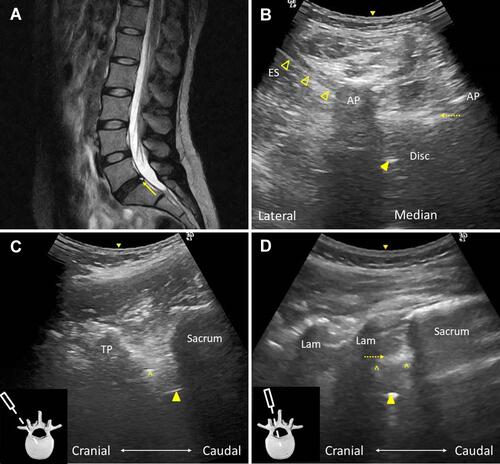
Figure 2 (A) Sagittal T2-weighted magnetic resonance (MR) imaging demonstrating a high-intensity zone (HIZ, arrow) of the L4/5 and L5/S1 intervertebral discs (IVDs) at the posterior annulus. (B) Axial ultrasound (US) imaging of the L4/L5 interlaminar space showing the in-plane injection of the L4/L5 IVD. Note the needle tip was blocked by the articular processes. Dashed arrow: posterior longitudinal ligament. Void arrowheads: needle shaft. (C) Paramedian sagittal oblique US imaging of the lumbar spine with the window between the tip of the transverse process and the superior articular process showing the needle tip (arrowhead) within the IVD. Note the IVD was situated between the two hyperechoic bony cortex of vertebrae (^). The small insert illustrates the transducer position and orientation.
Abbreviations: AP, articular process; ES, erector spinae; TP, transverse process.
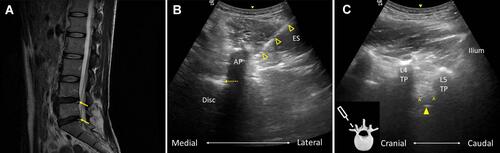
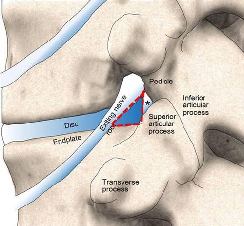
Figure 3 The Kambin triangle (red dashed line) bordered by the exiting nerve root (the hypotenuse), the thecal sac (the asterisk, the height), and the superior border of the caudal vertebra (the width). Note the anatomic relationships of the transverse process, the exiting nerve root, and the intervertebral disc and the facet joint from cranial to caudal.