
Figures & data
Figure 1 Although the L1 and L2 vertebra are wedge shaped at the T2 weighted imaging of magnetic resonance imaging (MRI) (A), the high signal of the short time inversion recovery (STIR) sequence was only seen in the L1 vertebral body (B). Twelve hours after the PKP, a high signal aggregation in front of the spinal cord from T12 to L1 was detected at the sagittal ((C), red arrow) plane of MRI examination, which gathered in the left part of the spinal canal at the axial plane of MRI ((D), red arrow).
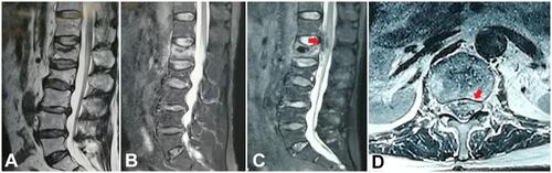
Figure 2 At the biplane monitoring, the puncture (A, B), balloon dilatation (C, D), and cement injection (E, F) were performed stepwise. Notably, when the needle arrived at the posterior wall of the vertebral body in the sagittal plane of fluoroscopic view, the intraoperative puncture revealed extension of the puncture needle beyond the inner edge of the projection of the pedicle in the coronal plane, suggesting a large abduction angle of the needle (A, B).
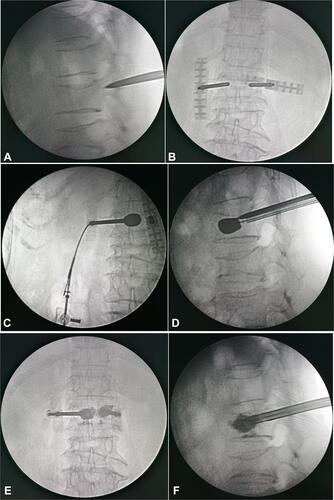
Figure 3 No intraspinal cement leakage was obvious on the anteroposterior (A) and lateral (B) view of the postoperative lumbar radiograph.
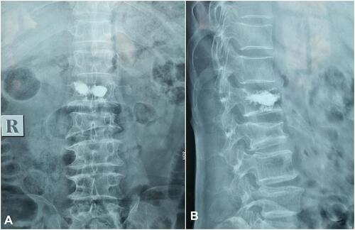
Figure 4 While there was no obvious intraspinal cement leakage on the postoperative lumbar computed tomography, there is visible dispersion of the bone cement on the left side of the vertebral body along the puncture trajectory, whose extension line is medial to the inner wall of the pedicle.
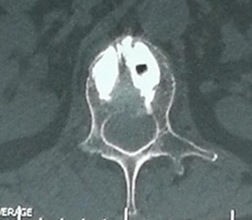
Table 1 Surgical Level, Anticoagulants, Symptoms, Cause Analysis, and Clinical Outcome for the Cases with Iatrogenic SEH after PKP or PVP