Figures & data
Figure 1 FABER Test (Patrick’s Test) – With the patient in a supine position, the lower extremity ipsilateral to the patient’s painful SIJ is correctly positioned by lying their lateral ankle on the contralateral anterior thigh. Then with the clinician standing on the side of the painful SIJ, one hand must stabilize the contralateral ASIS with firm pressure, while simultaneously applying a downward force through the ipsilateral flexed, externally rotated and abducted lower extremity, as depicted by the arrow.
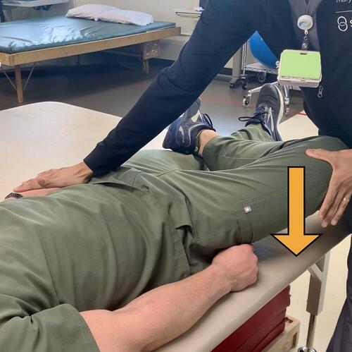
Figure 2 Thigh Thrust Test (Posterior Shear Test) – With the patient lying in a supine position the hip and knee ipsilateral to the painful SIJ are flexed, and the femur is positioned perpendicular to the table. A linear downward force through the femur towards the table is applied as depicted by the arrow.
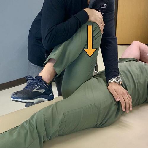
Figure 3 Gaenslen Test – While stabilizing a patient’s flexed knee, a counter force depicted by the arrow is applied through the hanging leg towards the floor.
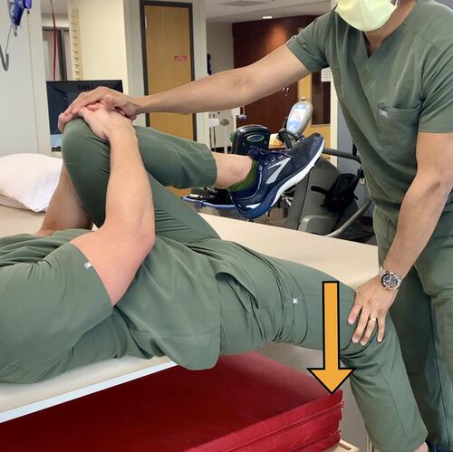
Figure 4 Gaenslen Test (modified technique) – With the patient lying in a lateral decubitus position, the painful SIJ is away from the table and contralateral leg is flexed toward the patient’s chest (similar to the traditional Gaenslen test). The Examiner stands behind the patient, who is positioned at the edge of the bed. Then stabilize the pelvis using one hand by applying a firm anterior pressure, and then extends the patient’s lower extremity at the hip ipsilateral to the painful SIJ as depicted by the arrow. Consider this modified test for those who are unable to lay supine.
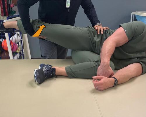
Figure 5 Compression Test – The patient is positioned in a lateral decubitus position, facing away from The Examiner, and their painful SIJ facing away from the table. While standing at the level of the pelvis, The Examiner applies a firm downward force through the ilium as seen by the arrow.
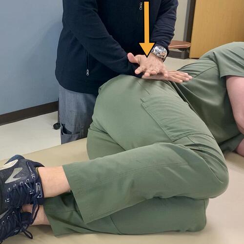
Figure 6 Distraction Test – With the patient supine, the clinician applies a downward and lateral force, away from midline, through the patient’s ASIS as depicted by the two arrows.
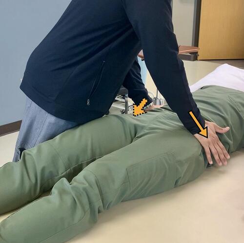
Figure 7 (A) Coronal view sacral T2 MRI with enhancement depicted by yellow arrows. (B and C) Axial and coronal view T1 MRI, respectively, showing post contrast enhancement depicted by yellow arrows. When these findings are seen concurrently in a patient, it is representative of bone marrow edema, which can be a sign of sacroiliitis.
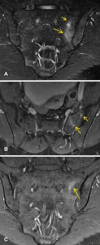
Figure 8 Anterior-posterior radiograph of pelvis showing joint space narrowing, some subcortical sclerotic changes (yellow arrows), anterior sacral osteophyte formation, and joint surface irregularity which is seen in osteoarthritis of the SIJ.
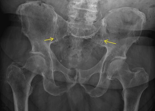
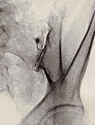
Figure 9 A fluoroscopic guided intra-articular SIJ injection utilizing the inferior joint approach. The fluoroscope is placed in contralateral oblique positioning. Typically oblique positioning is between 5 and 15 degrees, until the anterior and posterior sacroiliac joint lines intersect at the most inferior aspect of the joint.
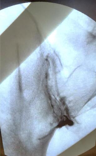
Figure 10 A fluoroscopic guided intra-articular SIJ injection utilizing a mid-body entrance. The fluoroscope is placed in contralateral oblique positioning. Compared to the inferior joint approach, cranial tilt and a great degree of obliquity is required. The obliquity is performed until the anterior and posterior sacroiliac joint lines intersect at the midbody of the joint.