
Figures & data
Figure 1 The patient was laid in the prone position on the CT imaging bed, with a pillow under the abdomen, the positioning grid was fixed on the surgical area with adhesive tape as (a) CT (Siemens Joy single row, parameter 81 mas/80 kV) vertical scanning was used to locate the plane of the L5-S1 intervertebral space. The plasma needle attempt to reach the disc plane require tilt angle puncture as shown in (b).
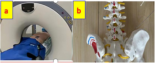
Figure 2 Based on the vertical CT scan images, we confirm the target point A, cross point B on the iliac crest and cross point C on the skin at the plane of L5/S1 (a). Because there will be obstruction by the iliac crest in the same plane, we will lift point C to reach the truly ideal puncture point A’ through cross point B’ on the iliac crest (b and c). The plasma puncture probe through A’ point slowly reached the A guided by different vertical CT scans plane (d–f).
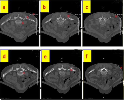
Figure 3 The vertical CT scanning was used to locate the plane of the L5-S1 intervertebral space and confirm A, B, C points (b). The CT tilted angle to make the puncture path without obstruction (a and c), Find the puncture point A’ on the skin, and the plasma puncture probe through A’ point slowly reached the A guided by tilt CT scans (d).
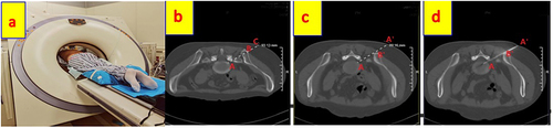
Table 1 Compare with the General Information of the Two Groups
Table 2 Comparison of Observational Indicators Between the Two Groups of Patients (Puncture and Scan Numbers and Surgery Time)
Table 3 Comparison of Preoperative and Postoperative Various Time Points NRS Scores in Group A {score, M (IQR)}
Table 4 Comparison of Preoperative and Postoperative Various Time Points NRS Scores in Group B{score, M (IQR)}
Table 5 Comparison of NRS Scores Before and After Treatment Between the Two Groups