Figures & data
Figure 1 Standard bone graft delivery funnel.
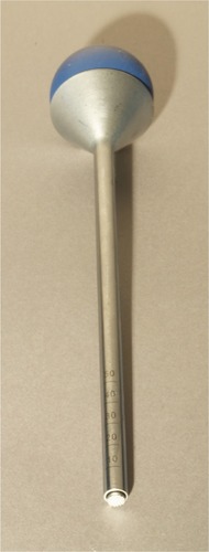
Figure 2 Conventional end-dispensing cannula ejects BG directly in the path of a fusion cage and does not distribute BG into the periphery of the prepared disk space.
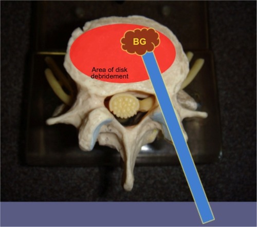
Figure 3 A removable funnel prevents obscuring the view of the tip of the cannula.
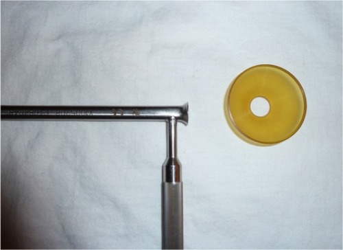
Figure 4 View of the cross section of the bone graft delivery tool relative to the conventional cylindrical tool.
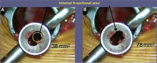
Figure 5 Close up of the bone graft delivery tool tip and its radiographic appearance.
Abbreviation: BG, bone graft.
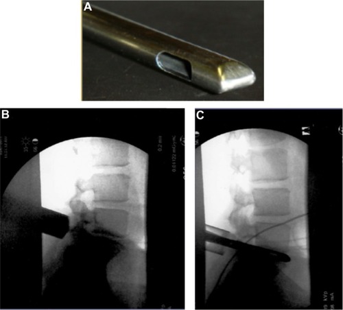
Figure 6 Axial view of the prepared disk space during and after application of the bone graft delivery tool.
Abbreviation: BG, bone graft.
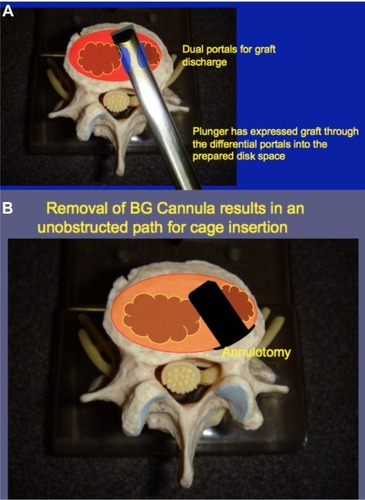
Table 1 Details of the study subjects, L4-5 disk space
Table 2 Details of the study subjects, L5-S1 disk space
Figure 7 Volumetric measurement of disk material removed and bone graft to be delivered.
Abbreviation: BG, bone graft.
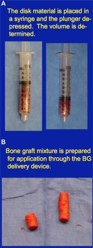
Figure 8 BG delivered versus disk material removed from the L4-S1 disk spaces.
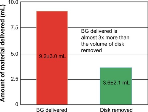
Figure 9 Relationship of BG delivered as a function of DMR.
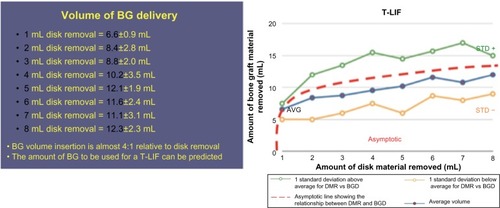
Figure 10 CT scan of the L5-S1 disk space showing complete filling of the prepared disk space and successful fusion and incorporation of bone graft 15 months postfusion.
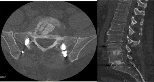
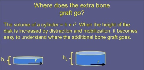
Figure 11 Geometric explanation for increased volume in a prepared, distracted disk space.