
Figures & data
Figure 1 Typical syringe and tubing set for CT/MRI contrast media injection.
Abbreviations: CT, computed tomography; MRI, magnetic resonance imaging.
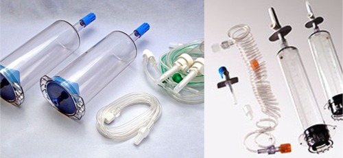
Figure 2 CT dual volume injector using bottles instead of syringes.
Abbreviation: CT, computed tomography.
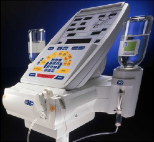
Figure 3 Single head injector for CT injections with injector head, syringe, and the control computer system.
Abbreviation: CT, computed tomography.
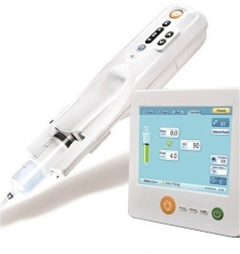
Figure 4 Effect of MRI contrast agent.
Abbreviation: MRI, magnetic resonance imaging.
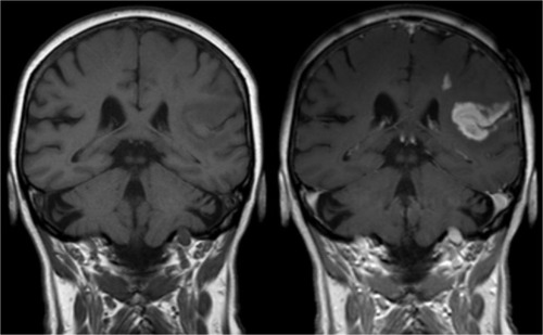
Table 1 MRI contrast media injection protocols – standard contrast media volume and standard flow rate for all manufacturers – only 1 or 2 mL/s flow rates are recommended
Table 2 MRI CMI manufacturers and some important specifications
Figure 5 Magnetic Resonance CMI operating at magnetic field strength of up to 9.4 T due to a hydraulic drive.
Abbreviation: CMI, contrast media injector.
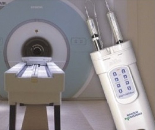
Figure 6 3 T MRI systems – oxygen tank was pulled into the magnet.
Abbreviation: MRI, magnetic resonance imaging.
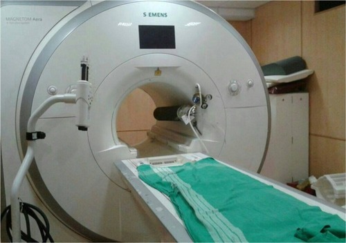
Table 3 What is really needed and what is optional for a CT/MRI power injector?