
Figures & data
Figure 1 The Intellijoint HIP 3D mini-optical navigation tool.
Notes: The camera (A), enclosed in its sterile drape, is attached to the pelvic platform (B) via 2 screws (C). The tracker (D) is magnetically attached to the femur platform (E). The camera captures the movements of the tracker when registering the native orientation or while trialing the implant components and thereafter relays the information to a workstation for review by the surgeon.
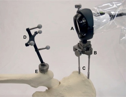
Figure 2 The Intellijoint HIP system.
Notes: The camera (A) is enclosed within a sterile drape (B) and fixed to the pelvis via a pelvic platform (C). The camera transmits positional data for display on the workstation (D), placed outside of the sterile field. Control buttons on the camera (E) allow the surgeon to interact with the system and manipulate the workstation display without leaving the sterile field.
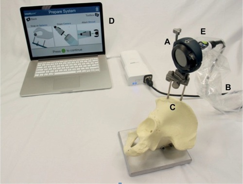
Figure 3 Representative images of the workstation screen indicating data provided to surgeons in real time.
Notes: Measurements of leg length and offset (A) and cup position (B) are displayed during trialing and once sizing is finalized. A summary page (C) displays all relevant data for review.
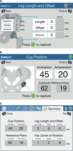
Figure 4 The acetabular benchtop phantom.
Notes: Discrete angles, confirmed by a calibrated electronic level, provide reference angles, which are then measured by the navigation tool. During testing, angles are computed from the movement of the tracker (A) captured by the camera (B).
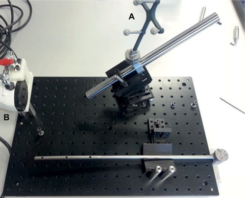
Figure 5 Benchtop phantom configured for leg length and offset testing.
Note: The camera (A) captures the position of the tracker (B) as it is moved about the simulated hip joint (arrow).
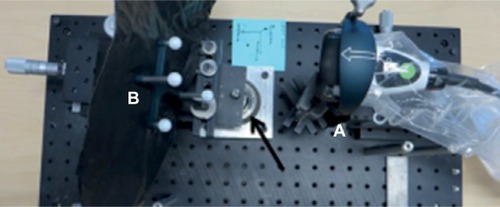
Table 1 Summary of the differences between the reference values and the values measured by the navigation tool