Figures & data
Table 1 Actuators and the rating for use in an MRI
Figure 1 Resulting force depending on the cross-sectional area.Citation27,Citation28
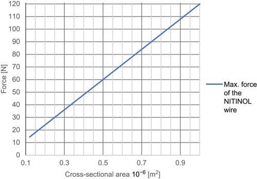
Figure 2 Needed energy to heat up the material NITINOL.
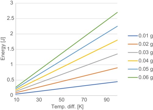
Figure 3 Measurement setup to evaluate the required energy of the nitinol wire, the time to switch over and the travel range (A) and determining the force (B).
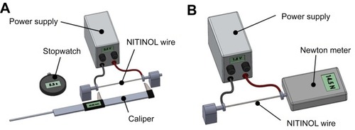
Figure 4 Measurement setup for NITINOL switch inside an MRI (NITINOL switch is outside).
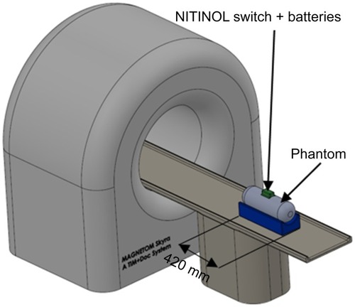
Figure 5 Measurement setup for NITINOL switch inside an MRI (NITINOL switch is inside).
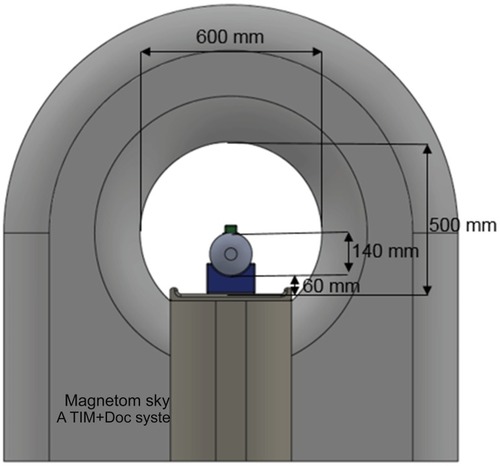
Table 2 Values of the switching time of the NITINOL wire (45 mm length and 0.392 mm diameter) at different voltages
Table 3 Force achieved directly with a 0.392 mm diameter NITINOL wire (l=45 mm)
Table 4 Measurement of power consumption and the calculated cycles to actuate the NITINOL wire
Figure 6 NITINOL switch with opened shell.
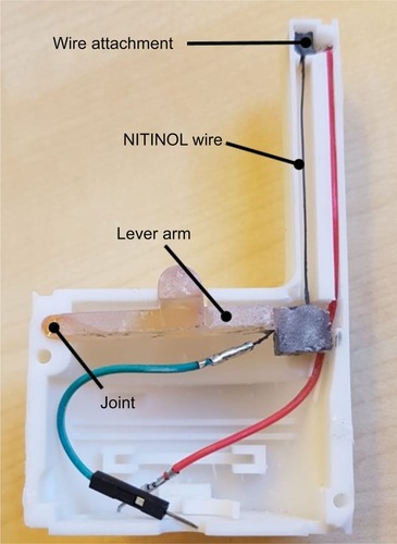
Figure 7 NITINOL switch with a closed shell.
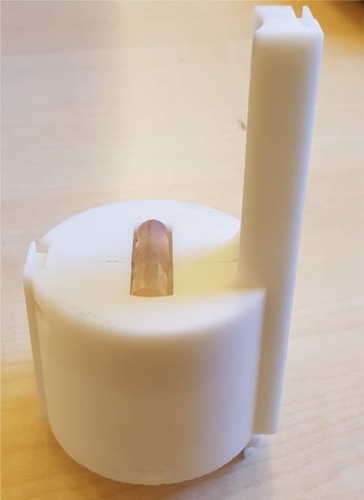
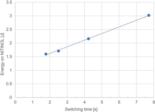
Figure 8 Average energy on NITINOL dependent on the switching time.