Figures & data
Table 1 Cephalometric Analysis
Figure 1 Patient initial facial and intraoral photos.
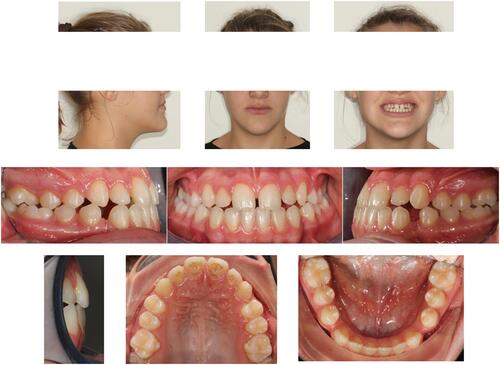
Figure 2 Initial records of the patient. (A) Lateral headfilm. (B) Cephalometric tracing. (C) Panoramic radiograph.
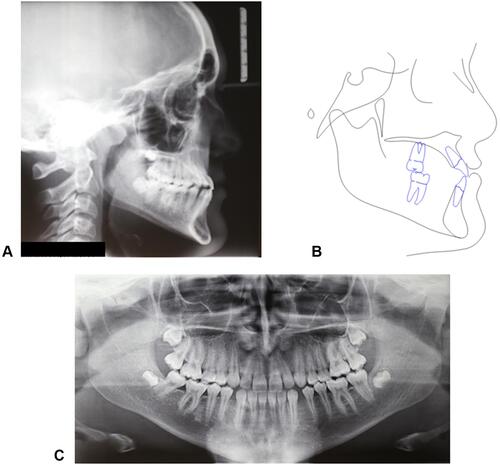
Figure 3 STL files of CBCT and dental arches. (A) before alignment. (B) After alignment.
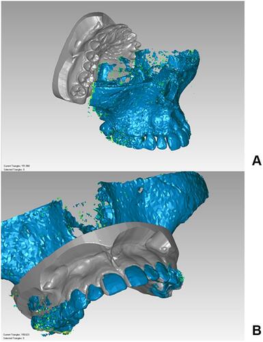
Figure 4 Determination of reference planes and axes on the maxilla. (A) Skeletal landmarks utilized: point on oral aspect of midpalatal suture at the level of second premolars (MS5) and second molars (MS7), most posterior point of vomer (VP), most lateral point of the zygomatic process of the maxilla on the right (ZR) and left side (LZ). (B) Midsagittal plane (MP), in blue, passing through MS5, MS7, and VP. (C) Horizontal palatal plane (HPP), in light blue, perpendicular to MP and passing through MS5 and MS7. (D) Center of Maxilla (CM) point, defined by the intersection of the projection of the bizygomatic line (ZR’-ZL’) to HPP and posterior part of midpalatal suture (MS5-MS7 line). (E) CM point as the origin of the x, y, z coordinate system of the maxilla.
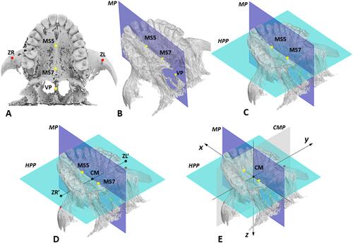
Figure 5 Setting of MSE in the maxilla in the initial default position. (A) Virtual model of MSE appliance with 4 micro-implants; the center of the appliance (CA), the light blue dot, is computed as the midpoint of the center of 4 micro-implant slots (yellow dots) and is set as the origin of MSE coordinate system. (B) MSE located in the initial default position in the maxilla, in which the CA point is coincident with the center of maxilla (CM) point, and the MSE x’, y,’ z’ coordinate system is aligned with the maxilla x, y, z system.
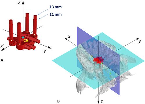
Figure 6 (A) User interface developed with Rhinoceros software, with which the inclination (Yaw, Pitch, and Roll) and position (dx, dy, dz) of MSE appliance can be changed to optimize the bone thickness (BT) at the level of the 4 micro-implants identified with numbers 1–4, the appliance distance from the palatal mucosa (DM), the micro-implant length required to obtain bicortical engagement (ML) and the guiding bar interference (GBI). (B) yaw, pitch, roll, and reference axes for MSE.
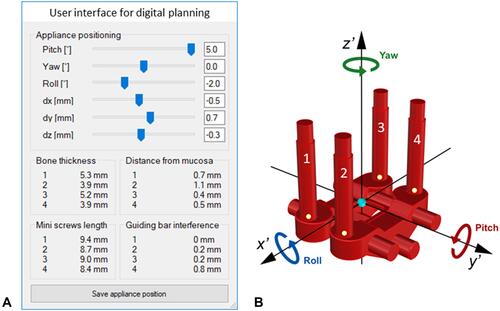
Table 2 Parameters Utilized for the Digital Planning of MSE Position and Inclination, and Their Clinical Significance
Figure 7 Parameters analyzed during the digital planning of MSE position and inclination: minimum micro-implant length required to obtain bicortical anchorage (ML), appliance distance from palatal mucosa (DM), bone thickness at the level of the micro-implant insertion sites (BT), guiding bar interference (GBI) with palatal mucosa. (A) sagittal section. (B) coronal section.
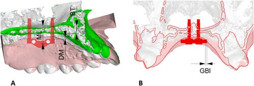
Figure 8 Lab work for MSE. (A) Virtual model with the final position of MSE after digital planning. (B) Digital design of positioning guide. (C) Fixation of the MSE appliance in the positioning guide with steel ligatures. (D) Positioning of the MSE appliance on the dental stone model by means of the resin guide for bending and welding of MSE arms.
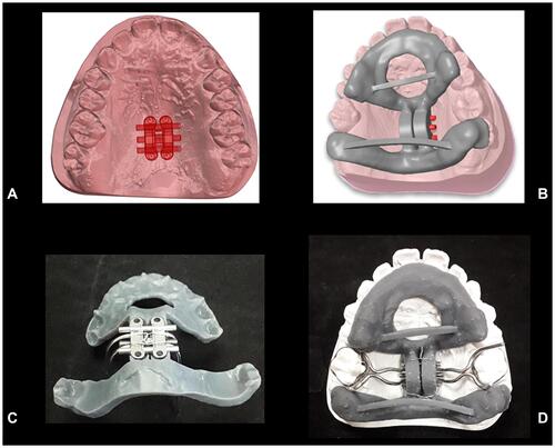
Figure 9 (A) Finalized MSE appliance on the dental stone model. (B) MSE appliance after placement in the patient oral cavity. (C) Intraoral picture after maxillary expansion.

Figure 10 Patient wearing the facemask. (A) Frontal view. (B) Lateral view.
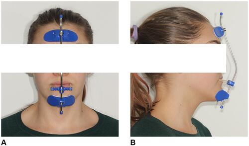
Figure 11 Patient CBCT after expansion, before the start of maxillary protraction. (A) Axial palatal section. (B) Maxilla 3D rendering.
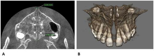
Figure 12 Final records of the patient. (A) Final lateral headfilm. (B) Final cephalometric tracing. (C) Superimposition of pre-treatment (black) and post-treatment (red) cephalometric tracings on anterior cranial base at Sella.
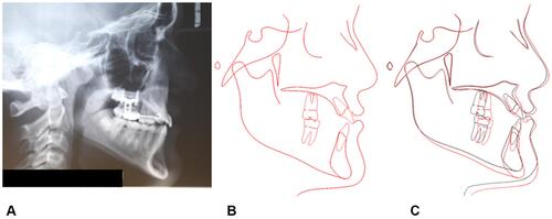
Figure 13 Facial and intraoral pictures after facemask therapy.
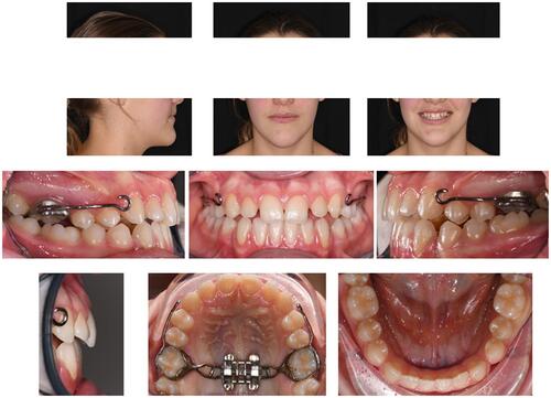
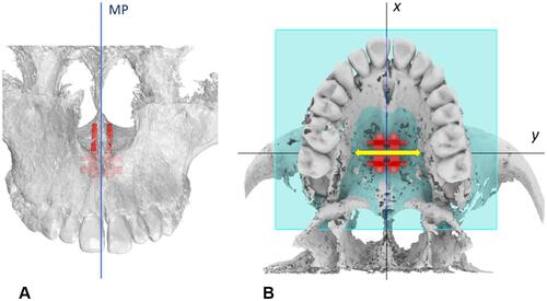
Figure 14 MSE initial default position. (A) Parallelism between the micro-implants and the midsagittal plane (MP) and nasal septum. (B) MSE expansion force vector (yellow arrow) positioned perpendicularly to the midpalatal suture.